By the end of this chapter you should be able to:
Write the coenergy of a two-winding system and identify its mutual term.
Derive the three components of torque and say which survives when the rotor is cylindrical.
Explain why the mutual torque can be reversed whereas a singly excited force cannot.
Describe torque development by the alignment of two fields for soft iron, a permanent magnet and an electromagnet.
Identify the stable and unstable positions in each case, and the period of the torque.
Derive \(T = 2BIlr\sin\theta = K_L\sin\theta\) geometrically and confirm it against the energy method.
Combine alignment and reluctance torque and find the angle of maximum total torque.
State the two methods of obtaining unidirectional torque and identify the machine each produces.
Two Windings, One Field
A doubly excited magnetic system has two windings sharing one magnetic circuit, with a movable member between them. Typically one winding is on the stationary member and the other on the rotating one — a field winding and an armature winding, in the language of Part 2.
Chapter 16 ended on a limitation. A singly excited system develops a force proportional to \(i^{2}\), so it can only attract, never repel, and reversing the supply changes nothing. That is enough for a relay but useless for a machine, which must be able to motor and to brake, to run forwards and backwards.
The second winding removes the limitation entirely. As Section 17-3 shows, a new torque term appears which is proportional to the product \(i_1i_2\) rather than to a square. Reverse one current and the torque reverses; reverse both and it does not. Every DC machine, every synchronous machine and every induction machine in this book runs on that term.
| Feature | Singly excited | Doubly excited |
|---|---|---|
| Excitations | One | Two |
| Torque depends on | \(i^{2}\) | \(i_1i_2\) (plus \(i^{2}\) terms) |
| Can torque reverse? | No | Yes |
| Needs saliency? | Yes — no variation, no force | No |
| Torque period | 180° (varies as \(\sin2\theta\)) | 360° (varies as \(\sin\theta\)) |
| Typical devices | Relay, solenoid, reluctance motor | DC, synchronous and induction machines |
Coenergy with Two Windings
With two windings the flux linkage of each depends on both currents:
and the coenergy, obtained by the same integration as in Chapter 15 but now over both currents in turn, is the expression already met in Chapter 14:
For a linear system this equals the field energy, as Chapter 15 established. All three coefficients — \(L_1\), \(L_2\) and \(M\) — may depend on the rotor angle \(\theta\).
Which of the three actually varies with angle depends on the geometry, and this is worth settling before any calculation:
\(L_1\), the stator self-inductance, varies with \(\theta\) only if the rotor is salient — a shaped rotor presents different reluctance at different angles.
\(L_2\), the rotor self-inductance, varies with \(\theta\) only if the stator bore is non-uniform, which for a slotted but essentially cylindrical stator it is not. In most machines \(L_2\) is constant.
\(M\), the mutual inductance, always varies with \(\theta\), being greatest when the two windings' axes coincide and zero when they are perpendicular:
\[M(\theta) = M_{\max}\cos\theta\]
The Three Components of Torque
The torque follows from Chapter 16's rule, differentiating the coenergy with respect to angle while holding both currents constant:
The first two terms are exactly the singly excited result of Chapter 16, one for each winding. The third is new, and it is the term that makes machines possible.
Substituting \(M = M_{\max}\cos\theta\) gives the alignment torque explicitly:
so \(T \propto \sin\theta\) — a result obtained quite differently in Section 17-7, from pure geometry.
If the rotor is cylindrical, \(L_1\) and \(L_2\) are constant, both reluctance terms vanish, and the alignment torque is all the torque there is.
A round-rotor synchronous machine or a DC machine works entirely on this term.
Because it depends on the product \(i_1i_2\), reversing either current reverses the torque; reversing both leaves it unchanged.
This is why a DC motor is reversed by swapping either the field or the armature connections, but not both.
Problem. A doubly excited system has \(L_1 = 0.30 + 0.05\cos2\theta\) H, \(L_2 = 0.20\) H (constant) and \(M = 0.15\cos\theta\) H. The currents are \(i_1 = 10\) A and \(i_2 = 5\) A. Find each torque component at \(\theta = 30^{\circ}\) and the maximum value of each.
Derivatives.
At \(\theta = 30^{\circ}\): \(\sin 30^{\circ} = 0.500\) and \(\sin 60^{\circ} = 0.866\), so
Maximum of each.
Comment. Both components are negative here, so both act to reduce \(\theta\) — pulling the rotor towards alignment. Note that they peak at different angles, 90° and 45°, because one varies as \(\sin\theta\) and the other as \(\sin2\theta\). The total therefore peaks somewhere between, as Section 17-8 works out precisely.
Note also that \(L_2\), being constant, contributes nothing at all. This is the usual situation: the rotor sees an essentially cylindrical stator bore, so only the stator self-inductance and the mutual inductance vary with angle.
Torque by the Alignment of Two Fields
The energy method gives the answer but not much physical insight. The classical approach reaches the same result by asking what happens when a magnetisable body is placed in an existing field and allowed to turn.
The following cases are considered to understand the process of torque development by the alignment of two fields:
Soft iron piece placed in the magnetic field.
Permanent magnet placed in the magnetic field.
Electromagnet placed in the magnetic field.
In each case a stationary main field \(F_m\) is produced by permanent magnets, and a rotatable member develops its own field \(F_r\). The angle between the two axes is the torque angle \(\theta\), and the torque acts to bring the two into line.
Soft Iron in a Magnetic Field
Consider a soft iron piece, capable of free rotation, placed in the magnetic field of two permanent magnets. The magnetic lines of force are set up in the soft iron piece.
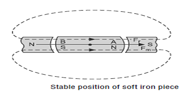
The molecular poles get aligned parallel to the magnetic field due to magnetic induction.
The soft iron piece obtains the polarities as marked.
This is the stable position of the soft iron piece.
Torque produced in this case is zero.
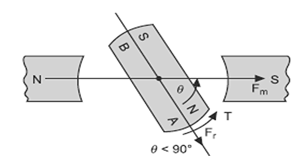
If the soft iron piece is rotated through an angle \(\theta\) (with \(\theta \lt 90^{\circ}\)), then by magnetic induction ends A and B become north and south poles respectively.
A force of attraction acts on the two ends and the soft iron piece will try to come in line with the main field — that is, the position of least reluctance path.
This anticlockwise torque tries to decrease the angle \(\theta\) and is considered as negative.
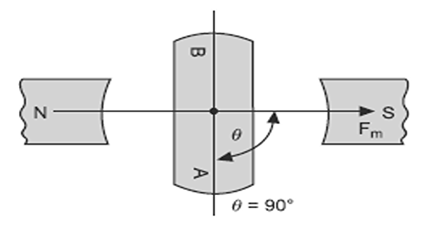
When the soft iron piece is rotated through an angle \(\theta = 90^{\circ}\), an equal force of attraction and repulsion acts on each end of the soft iron piece, therefore the torque produced is zero.
This is the unstable position of the soft iron piece, because a slight change in angle \(\theta\) in either direction will create a torque in that direction.
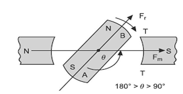
When the soft iron piece is rotated through an angle \(\theta \gt 90^{\circ}\), then by magnetic induction ends A and B become south and north poles respectively — the polarities have reversed.
The torque now acts to carry the piece onward to \(\theta = 180^{\circ}\), which is a second stable position identical in every respect to \(\theta = 0\).
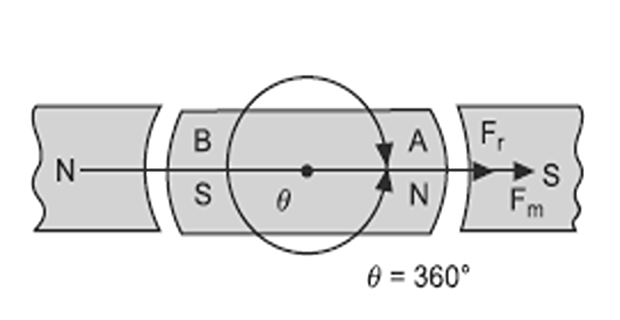
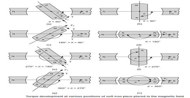
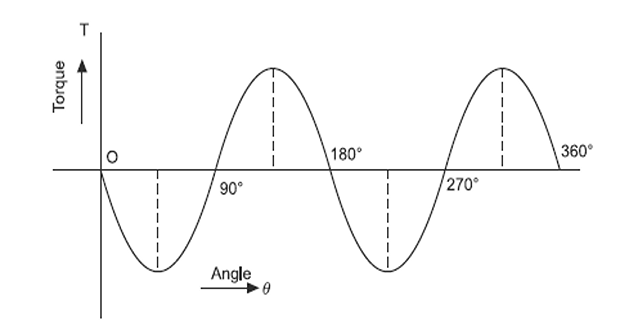
Because the induced polarities reverse as the piece passes 90°, the pattern repeats every 180°. There are stable positions at \(\theta = 0\) and \(180^{\circ}\), unstable positions at \(90^{\circ}\) and \(270^{\circ}\), and the torque varies as \(\sin2\theta\).
This is exactly the \(T = -i^{2}L_2\sin2\theta\) of Section 16-7. The soft iron piece has no excitation of its own, so it is a singly excited system in disguise — which is why it cannot tell one end of the main field from the other.
Permanent Magnet in a Magnetic Field
Replace the soft iron by a permanent magnet, free to rotate. Now the rotor has a polarity of its own, which travels with it.
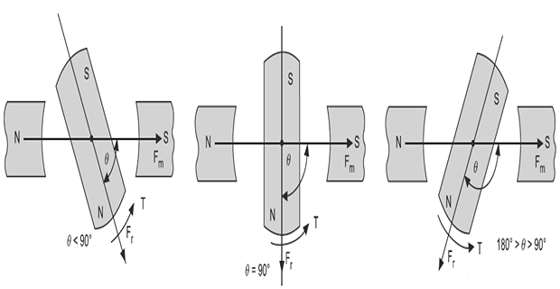
There is a force of attraction on the north and south pole of the rotating magnet which, being equal and opposite, cancel each other.
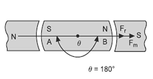
In this position the torque produced is zero, because the field of the rotating magnet \(F_r\) and the field of the stationary permanent magnet \(F_m\) are in line with each other.
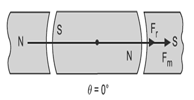
When the magnet is rotated through an angle \(\theta\) — less than 90°, equal to 90°, or more than 90° but less than 180° — its north pole will be attracted towards the south pole, and its south pole towards the north pole, of the stationary permanent magnets.
In other words, the rotor field \(F_r\) tries to come in line with the main field \(F_m\), and torque is developed.
This anticlockwise torque is considered negative, because it is decreasing the torque angle \(\theta\).
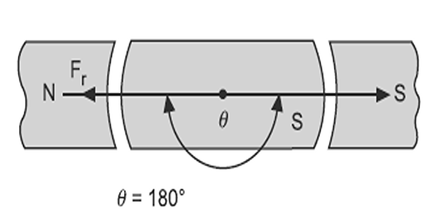
When the magnet is rotated through an angle \(\theta = 180^{\circ}\), the two fields \(F_r\) and \(F_m\) are in line with each other but acting in opposite directions.
Therefore the torque developed is zero, but this is the unstable position, because a slight change in angle \(\theta\) in either direction will create a torque in that direction and the rotor will not regain its original position.
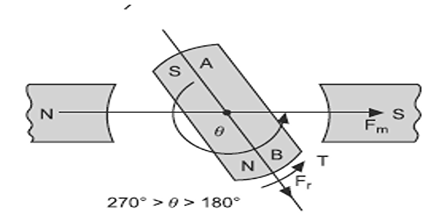
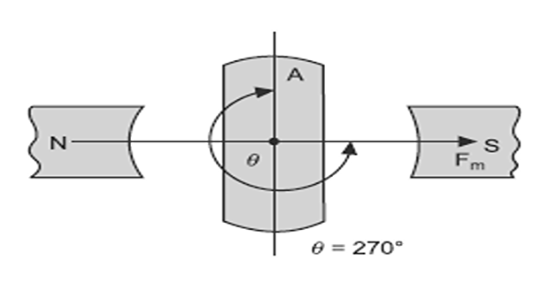
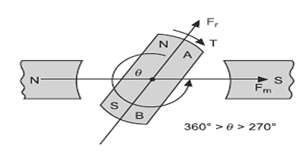
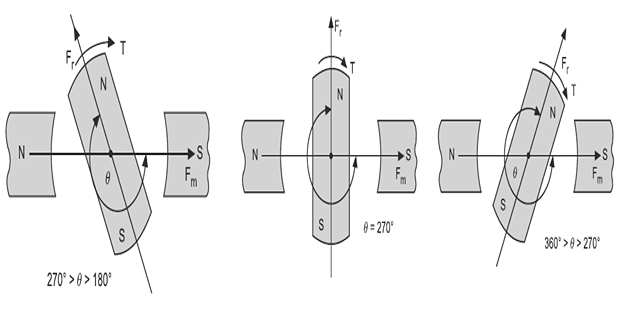
When the magnet is rotated through an angle \(\theta\) more than 180° but less than 360° — that is, less than 270°, equal to 270°, or more than 270° — its north and south poles will be attracted towards the south and north poles of the stationary permanent magnets respectively.
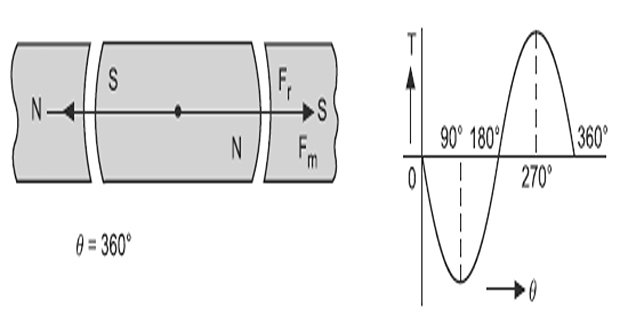
In other words \(F_r\) will again try to come into line with \(F_m\), but now the torque is positive, carrying the rotor onward towards \(360^{\circ}\) — which is the same position as \(0^{\circ}\).
Let
Torque is force times perpendicular distance. In the right-angled triangle oab, the distance perpendicular to the force is
and since both poles contribute equally,
Electromagnet in a Magnetic Field
Now replace the permanent magnet by an electromagnet — a coil of current-carrying conductors on a rotatable former. This is the actual armature of a machine, and the analysis gives the classical torque expression.
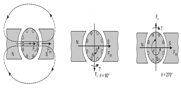
Let
In the right-angled triangle, the angle \(aob = \theta\), so the distance perpendicular to the force is
The total torque acting on the two conductors is therefore
The force on a current-carrying conductor in a field was established in Chapter 1 as \(F = BIl\), where
Torque is greatest at \(\theta = 90^{\circ}\), when the two field axes are perpendicular, and zero when they are in line.
This geometric derivation and the energy method of Section 17-3 give the same law:
The correspondence is exact. The main field \(B\) is produced by the field current \(i_1\), the conductor current \(I\) is \(i_2\), and the geometry \(2lr\) together with the field constant is what \(M_{\max}\) represents. The energy method reaches the result without ever mentioning a conductor, which is why it extends to machines where the currents flow in complicated distributed windings — the subject of Chapter 19.
Problem. A machine has a cylindrical rotor, so that \(L_1\) and \(L_2\) are constant and \(M = 0.12\cos\theta\) H. The currents are \(i_1 = 8.0\) A and \(i_2 = 4.0\) A. Find the torque at \(\theta = 30^{\circ}\) and its maximum. What happens if \(i_2\) is reversed?
Torque. With no saliency, only the alignment term survives:
At 30°.
Maximum.
Reversing \(i_2\). The product \(i_1i_2\) changes sign, so
The torque has reversed — the machine now drives the other way, or brakes.
Comment. Contrast this with Chapter 16, where reversing the current changed nothing whatever. The ability to reverse torque by reversing one excitation is the single most important practical consequence of double excitation, and it is why a DC motor is reversed by swapping either the field or the armature leads — but never both, which would leave the product unchanged.
Problem. An armature coil has two active conductors of effective length 0.25 m at a radius of 0.10 m, carrying 15 A in a main field of 0.80 T. Find the force per conductor, the torque constant \(K_L\), and the torque at \(\theta = 60^{\circ}\) and at maximum.
Force per conductor.
Torque constant.
Torque at 60°.
Checking directly from \(T = 2Fr\sin\theta = 2(3.00)(0.10)(0.866) = 0.520\) N·m \(\checkmark\)
Maximum torque. At \(\theta = 90^{\circ}\), \(T = K_L = 0.600\) N·m.
Comment. A single coil produces very little torque, which is why real armatures carry hundreds of conductors. Note also that the torque falls away as the coil approaches alignment — at 60° it has already lost 13 % of its peak, and at 30° it would deliver only half. Keeping the machine near \(\theta = 90^{\circ}\) is the whole purpose of the commutator, as Section 17-9 explains.
Combined Alignment and Reluctance Torque
Most real machines have both components. A salient-pole synchronous machine has a shaped rotor, so \(L_1\) varies with angle, and a field winding, so \(M\) varies too. The total torque is the sum:
where \(\delta\) is the torque angle — called the load angle in Chapter 76 — and the two coefficients come from the alignment and reluctance terms respectively.
Problem. A salient-pole machine has \(T = 240\sin\delta + 60\sin2\delta\) N·m. Find the torque at \(\delta = 30^{\circ}\), \(45^{\circ}\), \(60^{\circ}\) and \(90^{\circ}\), and the angle and value of maximum torque. Compare with an equivalent cylindrical machine.
| \(\delta\) | Alignment (N·m) | Reluctance (N·m) | Total (N·m) |
|---|---|---|---|
| 30° | 120.0 | 52.0 | 172.0 |
| 45° | 169.7 | 60.0 | 229.7 |
| 60° | 207.8 | 52.0 | 259.8 |
| 68.5° | 223.3 | 40.9 | 264.2 |
| 90° | 240.0 | 0.0 | 240.0 |
Angle of maximum torque. Setting the derivative to zero:
Using \(\cos2\delta = 2\cos^{2}\delta - 1\) and dividing by 120:
Comparison. A cylindrical machine with the same alignment coefficient would peak at \(240\) N·m at \(\delta = 90^{\circ}\). Saliency has raised the peak by 10.1 % and moved it back to 68.5°.
Comment. Two practical consequences follow, and both matter in Chapter 76. A salient machine produces more torque than a cylindrical one of the same rating, at no cost in excitation — the extra comes free from the rotor's shape. And because the peak occurs at a smaller angle, the machine has a wider margin of stability: it reaches maximum torque before the load angle has grown dangerously large.
Note also that beyond 90° the reluctance term turns negative and works against the alignment term, which is why the total curve falls below the alignment curve in the right-hand half of the figure.
Production of Unidirectional Torque
There is a difficulty with everything above, and it is fundamental. By the alignment of two fields torque develops, but the torque produced is not unidirectional.
The reason is visible in the figure of Section 17-8. As the rotor turns, \(\theta\) changes, the torque falls to zero at alignment and then reverses. Left alone, the rotor would oscillate about the aligned position and settle there — which makes an excellent compass needle but a useless motor.
By rotating the main magnets, so that they drag the other magnets — or the armature, or electromagnet — free to rotate along with them, because of the tendency of the field of the freely rotating magnet or armature to align with the field of the main magnet.
By changing the direction of flow of current in the conductors of the electromagnet (armature) in such a manner that the conductors facing a particular main field pole always have the same direction of current flow.
Rotating the main field is achieved electrically, not mechanically, by the three-phase winding of Chapter 59. The rotor is then dragged round with it.
If the rotor keeps exact step, the machine is synchronous (Part 5). If it lags slightly so that its currents are induced, it is an induction motor (Part 4).
Switching the conductor currents as they pass from pole to pole is the job of the commutator and brushes.
The result is that \(\theta\) is held near 90° whatever the rotor position, so the torque stays at its maximum and never reverses. This is Chapter 22's subject.
Problem. A doubly excited machine has a field current of 6.0 A, an armature current of 20 A, and \(\mathrm{d}M/\mathrm{d}\theta = 0.080\) H/rad at the operating point. Find the torque. What is the torque if (a) the armature current is reversed, (b) the field current is reversed, and (c) both are reversed?
Torque.
| Case | \(i_1\) | \(i_2\) | Torque (N·m) | Effect |
|---|---|---|---|---|
| Normal | +6 | +20 | +9.60 | Motoring forward |
| (a) Armature reversed | +6 | −20 | −9.60 | Torque reverses |
| (b) Field reversed | −6 | +20 | −9.60 | Torque reverses |
| (c) Both reversed | −6 | −20 | +9.60 | No change |
Comment. Case (c) is the one that catches people out. Reversing the supply to a DC motor reverses both currents at once, so the machine carries on turning the same way — which is exactly why a series motor runs on AC and became the universal motor of Chapter 92.
To reverse a DC machine, one connection must be swapped and only one. In practice it is the armature, because the field winding is highly inductive and switching it produces a large voltage transient — and because the flux takes time to reverse, making armature reversal much quicker.
Summary and Key Formulas
A doubly excited system has two windings on one magnetic circuit. Its coenergy is \(W' = \tfrac{1}{2}L_1i_1^{2} + \tfrac{1}{2}L_2i_2^{2} + Mi_1i_2\).
The torque has three components: two reluctance terms and one alignment term, \(T = \tfrac{1}{2}i_1^{2}\mathrm{d}L_1/\mathrm{d}\theta + \tfrac{1}{2}i_2^{2}\mathrm{d}L_2/\mathrm{d}\theta + i_1i_2\,\mathrm{d}M/\mathrm{d}\theta\).
With \(M = M_{\max}\cos\theta\) the alignment torque is \(-i_1i_2M_{\max}\sin\theta\). It survives without saliency and can be reversed.
Soft iron in a field has induced poles that reverse past 90°, giving stable positions at 0° and 180° and torque varying as \(\sin2\theta\) — it is reluctance torque.
A permanent magnet or electromagnet carries fixed polarity, giving one stable position at \(\theta = 0\), an unstable one at 180°, and torque varying as \(\sin\theta\).
Geometrically, \(T = 2Fr\sin\theta\), and with \(F = BIl\) this gives \(T = 2BIlr\sin\theta = K_L\sin\theta\), so \(T \propto \sin\theta\).
A salient machine has both components: \(T = T_1\sin\delta + T_2\sin2\delta\). Saliency raises the peak torque and moves it to an angle below 90°.
Alignment torque is not unidirectional. Continuous torque needs either a rotating main field (AC machines) or current switching in the armature (DC machines, by commutator).
| Quantity | Formula | Notes |
|---|---|---|
| Flux linkages | \(\lambda_1 = L_1i_1 + Mi_2\), \(\lambda_2 = Mi_1 + L_2i_2\) | two windings |
| Coenergy | \(W' = \tfrac{1}{2}L_1i_1^{2} + \tfrac{1}{2}L_2i_2^{2} + Mi_1i_2\) | linear system |
| General torque | \(T = \tfrac{1}{2}i_1^{2}\dfrac{\mathrm{d}L_1}{\mathrm{d}\theta} + \tfrac{1}{2}i_2^{2}\dfrac{\mathrm{d}L_2}{\mathrm{d}\theta} + i_1i_2\dfrac{\mathrm{d}M}{\mathrm{d}\theta}\) | three components |
| Mutual inductance | \(M(\theta) = M_{\max}\cos\theta\) | max when axes coincide |
| Alignment torque | \(T = -i_1i_2M_{\max}\sin\theta\) | reversible; no saliency needed |
| Reluctance torque | \(T = -i^{2}L_2\sin2\theta\) | needs saliency; not reversible |
| Geometric torque | \(T = 2Fr\sin\theta\) | two poles or two conductors |
| Conductor force | \(F = BIl\) | Chapter 1 |
| Classical result | \(T = 2BIlr\sin\theta = K_L\sin\theta\) | \(K_L = 2BIlr\) |
| Salient machine | \(T = T_1\sin\delta + T_2\sin2\delta\) | Chapter 76 |
| Maximum-torque angle | \(2\cos^{2}\delta + \dfrac{T_1}{T_2}\cos\delta - 1 = 0\) | from \(\mathrm{d}T/\mathrm{d}\delta = 0\) |
Common Mistakes
Writing the mutual term with a factor of one half. The self terms carry \(\tfrac{1}{2}\), the mutual term does not: \(Mi_1i_2\), not \(\tfrac{1}{2}Mi_1i_2\).
Assuming both self-inductances vary with angle. Usually only \(L_1\) does, because the stator bore is cylindrical and the rotor sees no variation.
Expecting alignment torque to need saliency. It does not — a perfectly round rotor still produces it, through \(\mathrm{d}M/\mathrm{d}\theta\).
Confusing the two torque periods. Alignment torque varies as \(\sin\theta\) over 360°; reluctance torque as \(\sin2\theta\) over 180°.
Treating the soft-iron case as alignment torque. Soft iron has no excitation of its own, so it is singly excited and produces reluctance torque only.
Placing the stable position at 90°. Torque is greatest at 90°, not zero; the stable position is at \(\theta = 0\) where the torque vanishes and any displacement is opposed.
Assuming the total torque peaks at 90°. With saliency it peaks earlier — 68.5° in Example 17.4.
Reversing both currents to reverse a machine. That leaves \(i_1i_2\) unchanged and the torque unchanged. Swap one only.
Forgetting the factor of two in \(T = 2Fr\sin\theta\). Both poles, or both conductors, contribute.
Believing alignment torque alone can run a motor. It reverses every half revolution. Continuous rotation requires commutation or a rotating field.
Chapter Review
Identify which inductances vary with angle before differentiating — constant terms contribute nothing.
P17.1 A doubly excited system has \(M = 0.20\cos\theta\) H with \(i_1 = 12\) A and \(i_2 = 6.0\) A, and a cylindrical rotor. Find the torque at 45° and its maximum.
Show answer
\[T = -i_1i_2M_{\max}\sin\theta = -(12)(6.0)(0.20)\sin\theta = -14.4\sin\theta ~\mathrm{N\,m}\]\[T(45^{\circ}) = -(14.4)(0.7071) = -10.2~\mathrm{N\,m}, \qquad T_{\max} = 14.4~\mathrm{N\,m} \text{ at } 90^{\circ}\]P17.2 For the system of P17.1, find the torque if \(i_1\) is reversed, and if both currents are reversed.
Show answer
\(i_1\) reversed: the product \(i_1i_2\) changes sign, so \(T = +14.4\sin\theta\) — the torque reverses.
Both reversed: the product is unchanged, so \(T = -14.4\sin\theta\) — no change.P17.3 An armature coil has two conductors of length 0.30 m at radius 0.12 m carrying 20 A in a field of 0.75 T. Find \(K_L\) and the torque at 40°.
Show answer
\[K_L = 2BIlr = 2(0.75)(20)(0.30)(0.12) = 1.080~\mathrm{N\,m}\]\[T = (1.080)\sin 40^{\circ} = (1.080)(0.6428) = 0.694~\mathrm{N\,m}\]P17.4 A system has \(L_1 = 0.40 + 0.08\cos2\theta\) H, \(L_2\) constant, and \(M = 0.18\cos\theta\) H, with \(i_1 = 8.0\) A and \(i_2 = 4.0\) A. Find both torque components at \(\theta = 60^{\circ}\).
Show answer
\[T_{\text{rel}} = \tfrac{1}{2}(64)\left(-0.16\sin 120^{\circ}\right) = (32)(-0.1386) = -4.44~\mathrm{N\,m}\]\[T_{\text{align}} = (32)\left(-0.18\sin 60^{\circ}\right) = (32)(-0.1559) = -4.99~\mathrm{N\,m}\]\[T = -9.43~\mathrm{N\,m}\]P17.5 A salient machine has \(T = 300\sin\delta + 80\sin2\delta\) N·m. Find the torque at 45° and 90°, and the maximum torque with its angle.
Show answer
\[T(45^{\circ}) = 300(0.7071) + 80(1) = 212.1 + 80.0 = 292.1~\mathrm{N\,m}\]Setting \(300\cos\delta + 160\cos2\delta = 0\) and using \(\cos2\delta = 2\cos^{2}\delta - 1\):\[T(90^{\circ}) = 300 + 0 = 300~\mathrm{N\,m}\]\[320\cos^{2}\delta + 300\cos\delta - 160 = 0 \quad\Longrightarrow\quad \cos\delta = 0.3796\]Saliency gives 11.2 % more peak torque than the 300 N·m of a cylindrical machine.\[\delta_{\max} = 67.7^{\circ}, \qquad T_{\max} = 300(0.9251) + 80(0.7024) = 333.7~\mathrm{N\,m}\]P17.6 A soft iron piece is placed in a magnetic field. State its stable and unstable positions and the period of its torque.
Show answer
Stable: \(\theta = 0\) and \(180^{\circ}\) — both aligned with the main field, since the induced polarities simply reverse.
Unstable: \(\theta = 90^{\circ}\) and \(270^{\circ}\) — the attracting and repelling forces balance, but any displacement grows.
Period: 180°, with torque varying as \(\sin2\theta\). The piece cannot distinguish the two ends of the main field because it has no polarity of its own.P17.7 Repeat P17.6 for a permanent magnet, and explain the difference.
Show answer
Stable: \(\theta = 0\) only.
Unstable: \(\theta = 180^{\circ}\).
Period: 360°, with torque varying as \(\sin\theta\).The difference is that a permanent magnet carries a fixed polarity that rotates with it, so it can distinguish the north end of the main field from the south. Soft iron's polarity is induced and flips as it turns, halving the period. This is precisely the distinction between alignment torque and reluctance torque.
P17.8 At what torque angle does a cylindrical machine deliver half its maximum torque, and what does this imply for a single-coil armature?
Show answer
A single-coil armature would therefore spend much of each revolution producing well under its peak torque, and none at all at alignment. Real armatures carry many coils spaced around the periphery, so that as one approaches alignment another is near 90°, keeping the total torque nearly constant. Chapter 23 develops this.\[\sin\theta = 0.5 \quad\Longrightarrow\quad \theta = 30^{\circ} \ \text{or} \ 150^{\circ}\]P17.9 State the two ways of obtaining unidirectional torque and name the family of machine each produces.
Show answer
1. Rotating the main field, so the rotor is dragged along by its tendency to align. Achieved electrically by a polyphase winding. Gives the synchronous machine (rotor in exact step) and the induction machine (rotor slipping, currents induced).2. Switching the armature current, so that conductors under a given main pole always carry current in the same direction. Achieved by the commutator and brushes. Gives the DC machine.
P17.10 A DC motor is to be reversed. Explain why swapping both the field and armature connections fails, and which is normally swapped in practice.
Show answer
Torque depends on the product \(i_1i_2\). Reversing both leaves the product unchanged, so the machine continues to turn the same way — the reason a series motor works equally well on AC.In practice the armature connections are swapped. The field winding is highly inductive, so interrupting it produces a large voltage transient, and its flux takes considerable time to reverse. Armature reversal is faster and electrically safer.
MCQ 1. The mutual term in the coenergy of two coupled windings is:
(a) \(\tfrac{1}{2}Mi_1i_2\) (b) \(Mi_1i_2\) (c) \(2Mi_1i_2\) (d) \(M(i_1+i_2)\)Show answer
(b) \(Mi_1i_2\) — no factor of one half, unlike the self terms.MCQ 2. Alignment torque requires:
(a) a salient rotor (b) two excitations (c) an air gap of zero (d) saturationShow answer
(b) two excitations. Saliency is not needed — a cylindrical rotor produces it perfectly well.MCQ 3. Reversing one of the two currents causes the alignment torque to:
(a) double (b) halve (c) reverse (d) stay the sameShow answer
(c) reverse, since it depends on the product \(i_1i_2\).MCQ 4. A soft iron piece in a magnetic field has stable positions at:
(a) 0° only (b) 0° and 180° (c) 90° only (d) 90° and 270°Show answer
(b) 0° and 180°. Its induced polarity reverses as it passes 90°, so both aligned positions are equivalent.MCQ 5. The torque on an electromagnet in a main field is greatest when the torque angle is:
(a) 0° (b) 45° (c) 90° (d) 180°Show answer
(c) 90°, since \(T = K_L\sin\theta\).MCQ 6. In \(T = 2BIlr\sin\theta\), the factor 2 accounts for:
(a) two poles of the main field (b) the two active conductors (c) the two windings (d) double frequencyShow answer
(b) the two active conductors of the coil, each contributing \(Fr\sin\theta\).MCQ 7. Reluctance torque varies with angle as:
(a) \(\sin\theta\) (b) \(\cos\theta\) (c) \(\sin2\theta\) (d) constantShow answer
(c) \(\sin2\theta\) — twice per revolution, unlike the alignment torque.MCQ 8. Compared with a cylindrical machine of the same alignment coefficient, a salient machine has a maximum torque that is:
(a) smaller, at 90° (b) larger, at 90° (c) larger, below 90° (d) the sameShow answer
(c) larger, below 90°. In Example 17.4 the peak rose 10.1 % and moved to 68.5°.MCQ 9. Unidirectional torque in a DC machine is obtained by:
(a) rotating the field (b) switching the armature current (c) saturating the iron (d) using a salient rotorShow answer
(b) switching the armature current, so that conductors under a given pole always carry current the same way. That is the commutator's job.MCQ 10. Reversing both the field and armature currents of a DC motor causes it to:
(a) reverse (b) stop (c) run the same way (d) run at double torqueShow answer
(c) run the same way. The product \(i_1i_2\) is unchanged — the principle of the universal motor.
Write the coenergy of a two-winding system and derive the three components of torque, stating which inductances vary with angle in a typical machine and why.
Explain why the alignment torque can be reversed while a singly excited force cannot, and what this makes possible.
Compare the behaviour of soft iron and a permanent magnet placed in the same field, accounting for the different periods of their torque.
Derive \(T = 2BIlr\sin\theta\) geometrically, and explain how it corresponds to the energy-method result.
Explain why a salient machine develops more torque than a cylindrical one, and why its peak occurs at a smaller angle.
Explain why alignment torque alone cannot drive a motor, and describe the two remedies together with the machine families they produce.
A single-coil armature produces torque proportional to \(\sin\theta\). Explain the consequence for smoothness of rotation and how real machines address it.
The torque equation is now complete for two windings, and Chapter 18 assembles the general force and torque results — extending to any number of windings, treating the saturated case where coenergy must be used with care, and separating alignment from reluctance torque in a form that Parts 2 to 6 can use directly.
From Chapter 19 the treatment turns practical. Real machines do not carry a single coil but a distributed winding spread over many slots, and the \(2BIlr\) of this chapter must be replaced by an mmf summed over the whole winding. That summation introduces the winding factors — distribution and pitch — which reduce the ideal EMF and torque by a few percent and which appear in every machine equation from Chapter 23 onward. With that, Part 1 ends at Chapter 19 and the DC machines of Part 2 begin.