By the end of this chapter you should be able to:
Explain why bulk DC generation has disappeared while DC drives have not.
List the duty requirements that make a DC machine the natural choice.
State the advantages and the brush-commutator penalty of DC machines.
Name the main parts of a DC machine and say what each does.
Draw the classification tree: separately excited and self-excited; shunt, series and compound.
Distinguish long-shunt from short-shunt and cumulative from differential compounding.
Write the current and EMF relations for each connection and use them in calculations.
Apply the generator and motor sign conventions correctly to the same machine.
The DC Machine Today
Part 1 established the principles. Part 2 applies them to the oldest and, in one important sense, the simplest machine — the one whose commutator holds the torque angle at 90° and so removes the complication of a moving field.
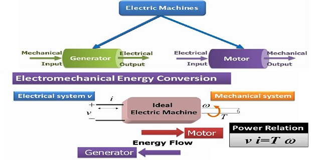
A DC machine is a versatile machine — the same machine can be used as a generator or as a motor.
The use of DC machines as DC generators to produce bulk power has rapidly disappeared, because of the economic advantages of AC generation and of AC transmission and distribution.
Today the need for DC power is often met by the use of solid-state controlled rectifiers.
Why DC Drives Persist
DC machines find extensive application wherever a drive must provide any of the following.
Constant mechanical power output, or constant torque, held over a working range rather than at one speed only.
Adjustable motor speed over wide ranges — achieved by armature-voltage and field-flux control, as Chapter 37 develops.
Precise speed or position control, to a degree that was difficult with AC machines before power electronics.
Efficient operation over a wide speed range, not merely at the design point.
Rapid acceleration and deceleration, since armature current — and therefore torque — can be changed almost instantly.
Responsiveness to feedback signals, which makes the DC machine the natural plant for a closed-loop control system.

Applications by Size
There is a wide variation in the size of DC motors, according to whether the application is short-term or continuous.
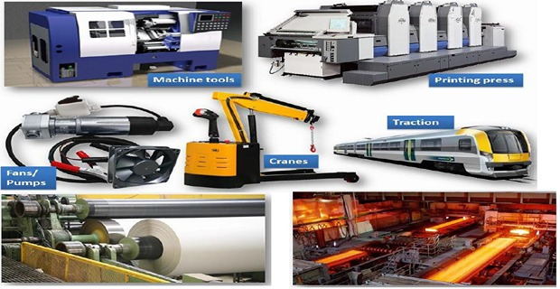
Used for small control devices, windscreen-wiper motors, fan motors, starter motors and various servomotors.
These run for seconds or minutes at a time, so they may be rated well above their continuous thermal capability.
Conveyors, pumps, hoists, overhead cranes, forklifts, fans, steel and aluminium rolling mills, paper mills, textile mills, various other rolling mills, golf carts, electric cars, street cars or trolleys, electric trains, electric elevators, and large earth-moving equipment.
The pattern in that list is worth noticing. Almost every entry involves either a heavy load that must be started from rest — hoists, cranes, trains, earth-movers — or a process whose speed must be held or varied precisely — rolling mills, paper mills, textile mills. Those are the two duties Section 20-2 identified, and they are why the DC machine held these applications long after AC machines had taken everything else.
Advantages and Disadvantages
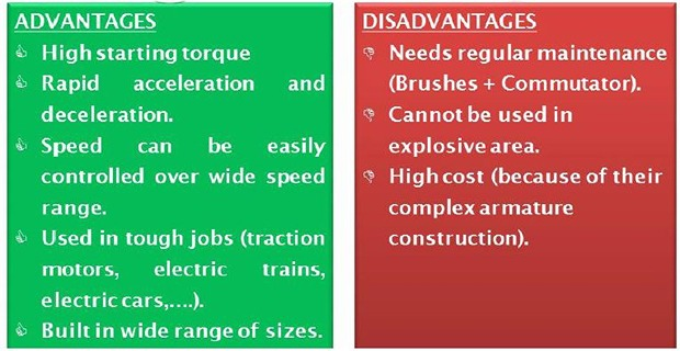
DC machine applications are very significant, but they are limited by the maintenance, wear and cost associated with the brush-commutator system. That single component is responsible for nearly every disadvantage in the table.
Simple and effective speed control over a wide range.
High starting torque, especially in the series machine.
Torque and flux are naturally decoupled, giving excellent dynamic response.
Straightforward four-quadrant operation — motoring and braking in both directions (Chapter 38).
Brush wear requires regular inspection and replacement.
Commutator maintenance — skimming, undercutting, and eventual replacement.
Sparking limits the machine in dusty or explosive atmospheres.
Higher cost and weight than an equivalent induction motor.
Speed and current are limited by commutation, not by the magnetics (Chapter 31).
Chapter 17 posed the unidirectional-torque problem and gave two answers. The DC machine takes the second: switch the armature current as the conductors pass from pole to pole, so that the torque angle stays at 90° and the torque never reverses. The device that does the switching is the commutator.
It works beautifully, and it is a set of sliding contacts carrying the full armature current. Every disadvantage above traces back to that one design decision, and the whole history of the last forty years — brushless DC machines, inverter-fed induction drives, vector control — is the story of getting the DC machine's behaviour without its commutator.
Anatomy at a Glance
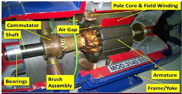
A brief orientation before the detailed treatment. Chapter 22 covers construction properly, Chapter 23 the commutator and Chapters 24 and 25 the armature windings; what follows is only enough to make the classification of Section 20-6 intelligible.
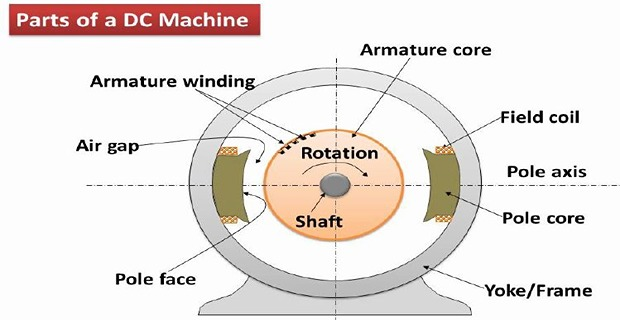
| Part | Where | Function |
|---|---|---|
| Yoke (frame) | Stationary, outermost | Mechanical support and return path for the flux |
| Pole cores and shoes | Stationary | Carry the field winding; spread the flux into the gap |
| Field winding | On the poles | Produces the main flux \(\Phi\) — the winding this chapter classifies |
| Armature core | Rotating | Laminated iron carrying the armature conductors |
| Armature winding | In the armature slots | Carries \(I_a\); seat of the generated EMF |
| Commutator | On the shaft | Switches the conductor currents — Chapter 23 |
| Brushes | Stationary, sliding | Connect the rotating winding to the external circuit |
| Interpoles | Between main poles | Improve commutation — Chapter 31 |
Classification by Excitation
DC machines are classified according to how the field winding is excited. There are two families and, within the self-excited family, three types.
In a separately excited machine it does not — the flux is fixed by an external supply, and the machine's behaviour is the simplest possible.
In a shunt machine the field sees the terminal voltage, which sags a little with load, so the flux falls slightly.
In a series machine the field carries the full load current, so the flux rises steeply with load — which is what gives the series motor its enormous starting torque.
In a compound machine both windings act, and the designer chooses whether they add or oppose.
Separately Excited Machines
The field winding is supplied from a source entirely independent of the machine — historically a small exciter, today a controlled rectifier. The armature circuit and the field circuit share nothing but the iron.
Because \(I_f\) is set independently, the flux \(\Phi\) is under the operator's direct control and does not change with load. This makes the separately excited machine the reference case against which the others are judged, and the natural choice wherever precise control is wanted.
Shunt, Series and Compound
A self-excited machine supplies its own field current. Three connections are possible.
| Type | Field current | Armature current | Generated EMF |
|---|---|---|---|
| Separately excited | External | \(I_a = I_L\) | \(E = V + I_aR_a\) |
| Shunt | \(I_{sh} = V/R_{sh}\) | \(I_a = I_L + I_{sh}\) | \(E = V + I_aR_a\) |
| Series | \(I_{se} = I_a\) | \(I_a = I_L\) | \(E = V + I_a(R_a + R_{se})\) |
| Compound, long-shunt | \(I_{sh} = V/R_{sh}\) | \(I_a = I_L + I_{sh}\) | \(E = V + I_a(R_a + R_{se})\) |
| Compound, short-shunt | \(I_{sh} = \dfrac{V + I_LR_{se}}{R_{sh}}\) | \(I_a = I_L + I_{sh}\) | \(E = V + I_aR_a + I_LR_{se}\) |
Long-shunt: the shunt field is connected across the series combination of armature and series field. The series field therefore carries \(I_a\).
Short-shunt: the shunt field is connected across the armature only. The series field therefore carries \(I_L\).
The numerical difference is small, as Example 20.3 shows, but the connections are not interchangeable in a design.
Cumulative: the series field mmf aids the shunt field mmf. Flux rises with load, so a generator's voltage is held up and a motor gets extra starting torque.
Differential: the series field opposes the shunt field. Flux falls with load.
Cumulative compounding is by far the more common; differential compounding is used only where a falling characteristic is wanted, and is prone to instability.
Problem. A shunt generator delivers 50 A at 230 V. The armature resistance is 0.10 \(\Omega\) and the shunt field resistance 115 \(\Omega\). Find the field current, the armature current and the generated EMF. Verify the power balance.
Field current. The shunt field sits across the terminals:
Armature current. The armature must supply both the load and the field:
Generated EMF.
Power balance.
Check: \(11\,500 + 270.4 + 460 = 12\,230\) W \(\checkmark\)
Comment. Note that the armature carries more than the load current, because it must also feed its own field. The field current is small — 4 % of the load here — but it is not negligible, and forgetting it is the commonest error in shunt-machine problems. Note also that the field copper loss, 460 W, exceeds the armature copper loss at this load.
Problem. A series generator delivers 40 A at 220 V. The armature resistance is 0.15 \(\Omega\) and the series field resistance 0.10 \(\Omega\). Find the generated EMF.
Currents. In a series machine there is only one current path:
Generated EMF.
Comment. The arithmetic is the simplest of the four types, but the machine is the most awkward. On no load there is no current, hence no field, hence no EMF — a series generator cannot build up voltage without a load, and its terminal voltage rises steeply as the load increases. That is why series generators are almost never used for supplying power, and appear mainly as boosters (Chapter 29).
Problem. A compound generator delivers 60 A at 250 V. The resistances are \(R_a = 0.12~\Omega\), \(R_{se} = 0.05~\Omega\) and \(R_{sh} = 125~\Omega\). Find the generated EMF for (a) long-shunt and (b) short-shunt connection.
(a) Long-shunt. The shunt field sees the terminal voltage:
(b) Short-shunt. Now the series field carries the load current, and the shunt field sees the terminal voltage plus the series-field drop:
Comparison. The two EMFs differ by only \(260.54 - 260.44 = 0.10\) V — less than 0.04 %.
Comment. The numerical difference is trivial, and students sometimes conclude the distinction does not matter. It matters for the field, not for the EMF. In long-shunt the series field carries \(I_a = 62.0\) A; in short-shunt it carries \(I_L = 60.0\) A. A designer sizing the series winding, or predicting how much the flux will boost at full load, must know which connection is used. Short-shunt is the more common in practice because the series winding then need not carry the field current as well.
Generator and Motor Conventions
The same machine works either way, and only one sign changes.
The machine is driven, and the generated EMF must exceed the terminal voltage to push current out:
Mechanical power in, electrical power out. \(EI_a\) is the power converted from mechanical form.
The machine is supplied, and the back EMF of Chapter 11 opposes the supply:
Electrical power in, mechanical power out. \(EI_a\) is the power converted to mechanical form.
with \(+\) for generator action and \(-\) for motor action. In either case \(EI_a\) is the converted power and \(I_a^{2}R_a\) is the armature copper loss.
A machine crosses smoothly between the two. If a motor is driven above the speed at which \(E = V\), the armature current reverses and it becomes a generator without any change of connection — which is precisely regenerative braking (Chapter 38).
Problem. A DC machine has \(R_a = 0.20~\Omega\) and operates at 220 V with an armature current of 40 A. Find the EMF and the converted power when it runs (a) as a generator and (b) as a motor. Account for the difference.
(a) As a generator.
(b) As a motor.
The difference.
Comment. The armature copper loss is \(I_a^{2}R_a = 320\) W in both cases, and the difference between the two converted powers is exactly twice that. The reason is that the loss is paid for from opposite ends: as a generator the mechanical input must cover both the electrical output and the loss, while as a motor the electrical input covers both the mechanical output and the loss. The loss therefore appears once on each side of the comparison.
Problem. A hoist must lift a load from rest and can tolerate a short overload of twice rated current. A candidate machine develops 150 N·m at its rated current of 40 A. Compare the torque available at 80 A from (a) a shunt motor and (b) a series motor, assuming no saturation.
Torque relations. Torque is proportional to \(\Phi I_a\) (Chapter 34). In a shunt motor the flux is fixed by the terminal voltage, so \(T \propto I_a\). In a series motor the flux is produced by the armature current itself, so below saturation \(\Phi \propto I_a\) and hence \(T \propto I_a^{2}\).
(a) Shunt motor.
(b) Series motor.
Comment. The series motor delivers twice the torque for the same overload current — which is why hoists, cranes and traction drives were series machines almost without exception. The price is that a series motor must never be run unloaded: with \(I_a\) small the flux is small, and since speed varies roughly as \(1/\Phi\), the machine can run away and destroy itself. Chapter 35 develops both characteristics properly.
Note the assumption stated in the problem. Once the series field saturates, \(\Phi\) stops rising with \(I_a\) and the torque reverts to being proportional to \(I_a\) — so the quadratic law holds only at moderate overloads.
Summary and Key Formulas
A DC machine is versatile — the same machine works as generator or motor. Bulk DC generation has disappeared; DC drives have not, and DC power now comes from solid-state controlled rectifiers.
DC drives persist where a duty demands constant torque or power, wide speed adjustment, precise control, efficiency across the range, rapid acceleration, or responsiveness to feedback.
Applications run from windscreen wipers and servomotors to rolling mills, hoists, traction and earth-moving equipment.
The great limitation is the brush-commutator system — wear, maintenance, sparking, cost, and a limit on speed and current set by commutation rather than by magnetics.
Machines are classified by how the field is excited: separately excited, or self-excited as shunt, series or compound.
Shunt: \(I_{sh} = V/R_{sh}\) and \(I_a = I_L + I_{sh}\). Series: \(I_a = I_{se} = I_L\). Compound: both, in long-shunt or short-shunt.
Cumulative compounding has the series field aiding the shunt field; differential has it opposing.
Generator: \(E = V + I_aR_a\) with \(E \gt V\). Motor: \(E = V - I_aR_a\) with \(E \lt V\). \(EI_a\) is the converted power in both.
| Quantity | Formula | Notes |
|---|---|---|
| Shunt field current | \(I_{sh} = V/R_{sh}\) | across the terminals |
| Shunt generator armature current | \(I_a = I_L + I_{sh}\) | armature feeds load and field |
| Shunt motor armature current | \(I_a = I_L - I_{sh}\) | line feeds both |
| Series machine | \(I_a = I_{se} = I_L\) | one current path |
| Long-shunt field current | \(I_{sh} = V/R_{sh}\) | series field carries \(I_a\) |
| Short-shunt field current | \(I_{sh} = \dfrac{V + I_LR_{se}}{R_{sh}}\) | series field carries \(I_L\) |
| Generator EMF | \(E = V + I_aR_a\) | plus \(I_aR_{se}\) or \(I_LR_{se}\) if compounded |
| Motor back EMF | \(E = V - I_aR_a\) | note the sign |
| Converted power | \(P_{\text{conv}} = EI_a\) | both machines |
| Armature copper loss | \(P_{cu} = I_a^{2}R_a\) | both machines |
| Shunt field copper loss | \(P_{f} = VI_{sh} = I_{sh}^{2}R_{sh}\) | — |
| Torque, shunt | \(T \propto I_a\) | flux constant |
| Torque, series | \(T \propto I_a^{2}\) | below saturation only |
Common Mistakes
Taking \(I_a = I_L\) in a shunt machine. The armature also feeds the field, so \(I_a = I_L + I_{sh}\) in a generator and \(I_L - I_{sh}\) in a motor.
Getting the shunt-motor current relation backwards. In a motor the line feeds both armature and field, so the armature gets less than the line current.
Using \(E = V + I_aR_a\) for a motor. The back EMF is less than the supply voltage; the sign reverses.
Applying the shunt field voltage to a short-shunt machine. There the shunt field sees \(V + I_LR_{se}\), not \(V\).
Confusing long-shunt with short-shunt by which winding looks longer. The names refer to the shunt path: long-shunt spans armature and series field; short-shunt spans the armature only.
Omitting \(R_{se}\) from the EMF equation of a series or compound machine. The series field resistance is in the armature circuit and its drop counts.
Assuming a series generator can build up on no load. No load means no current, no field and no EMF.
Running a series motor unloaded. With little current there is little flux, and the speed can rise destructively.
Applying \(T \propto I_a^{2}\) to a saturated series machine. Once the field saturates the flux stops rising and the law reverts to \(T \propto I_a\).
Thinking cumulative and differential are just a wiring detail. They give opposite load characteristics; differential compounding can make a machine unstable.
Chapter Review
Identify the machine type and whether it is generating or motoring before writing any equation — that decides every sign.
P20.1 A shunt generator delivers 80 A at 250 V with \(R_a = 0.08~\Omega\) and \(R_{sh} = 125~\Omega\). Find \(I_{sh}\), \(I_a\) and \(E\).
Show answer
\[I_{sh} = \frac{250}{125} = 2.00~\mathrm{A}, \qquad I_a = 80 + 2.00 = 82.0~\mathrm{A}\]\[E = 250 + (82.0)(0.08) = 250 + 6.56 = 256.6~\mathrm{V}\]P20.2 A series generator supplies 60 A at 240 V with \(R_a = 0.20~\Omega\) and \(R_{se} = 0.10~\Omega\). Find \(E\).
Show answer
\[I_a = I_{se} = I_L = 60~\mathrm{A}\]\[E = 240 + (60)(0.30) = 240 + 18.0 = 258~\mathrm{V}\]P20.3 A DC motor takes 45 A from a 230 V supply with \(R_a = 0.15~\Omega\). Find the back EMF and the converted power.
Show answer
\[E = V - I_aR_a = 230 - (45)(0.15) = 230 - 6.75 = 223.25~\mathrm{V}\]Check: input \(= (230)(45) = 10\,350\) W, armature loss \(= (2025)(0.15) = 304\) W, and \(10\,350 - 304 = 10\,046\) W \(\checkmark\)\[P_{\text{conv}} = EI_a = (223.25)(45) = 10\,046~\mathrm{W}\]P20.4 A short-shunt compound generator delivers 50 A at 220 V, with \(R_a = 0.10~\Omega\), \(R_{se} = 0.06~\Omega\) and \(R_{sh} = 110~\Omega\). Find \(E\).
Show answer
\[I_{se} = I_L = 50~\mathrm{A}, \qquad I_LR_{se} = (50)(0.06) = 3.00~\mathrm{V}\]\[I_{sh} = \frac{220 + 3.00}{110} = \frac{223}{110} = 2.027~\mathrm{A}, \qquad I_a = 50 + 2.027 = 52.03~\mathrm{A}\]\[E = 220 + (52.03)(0.10) + 3.00 = 220 + 5.203 + 3.00 = 228.2~\mathrm{V}\]P20.5 Repeat P20.4 for a long-shunt connection and compare.
Show answer
\[I_{sh} = \frac{220}{110} = 2.00~\mathrm{A}, \qquad I_a = 50 + 2.00 = 52.0~\mathrm{A}\]The two differ by only 0.12 V, but the series field carries 52.0 A in long-shunt against 50.0 A in short-shunt.\[E = 220 + (52.0)(0.10 + 0.06) = 220 + 8.32 = 228.3~\mathrm{V}\]P20.6 A shunt motor takes 60 A from a 240 V supply, with \(R_{sh} = 120~\Omega\) and \(R_a = 0.12~\Omega\). Find \(I_a\) and the back EMF.
Show answer
For a motor the line current splits between armature and field:\[I_{sh} = \frac{240}{120} = 2.00~\mathrm{A}, \qquad I_a = I_L - I_{sh} = 60 - 2.00 = 58.0~\mathrm{A}\]Note the subtraction in both places — this is where the generator and motor cases differ.\[E = 240 - (58.0)(0.12) = 240 - 6.96 = 233.0~\mathrm{V}\]P20.7 A motor develops 200 N·m at rated current. Find the torque at 1.5 times rated current if it is (a) shunt and (b) series, assuming no saturation.
Show answer
\[\text{shunt: } T = 200(1.5) = 300~\mathrm{N\,m}\]\[\text{series: } T = 200(1.5)^{2} = 200(2.25) = 450~\mathrm{N\,m}\]P20.8 Explain why a DC machine crosses from motoring to generating without any change of connection.
Show answer
The armature current is \(I_a = (V - E)/R_a\). As a motor \(E \lt V\) and \(I_a\) is positive. If the machine is driven faster — by a descending load, say — then \(E\) rises. When \(E = V\) the current is zero; beyond that \(E \gt V\) and the current reverses.With reversed current the torque also reverses and becomes retarding, while power flows back into the supply. The machine is now a generator, with nothing changed but its speed — the basis of regenerative braking (Chapter 38).
P20.9 Why is the DC machine's brush-commutator system described as both its answer and its problem?
Show answer
Chapter 17 showed that the torque from two aligned fields reverses every half revolution, so continuous rotation needs either a rotating field or current switching. The commutator provides the switching, reversing the conductor currents as they pass from pole to pole so the torque angle stays near 90° and the torque never reverses.But it does this with sliding contacts carrying the full armature current. Hence brush wear, commutator maintenance, sparking, restrictions in hazardous atmospheres, extra cost and weight, and a ceiling on speed and current set by commutation rather than by the magnetics. Every disadvantage of the DC machine follows from the device that makes it work.
P20.10 A traction drive must start a heavy train and then run at high speed with a light load. Which DC machine type suits the starting duty, and what precaution does it require?
Show answer
A series motor, because \(T \propto I_a^{2}\) below saturation gives very high torque at the large currents drawn from rest — exactly what a heavy train needs.The precaution: a series motor must never be allowed to run with little or no load. Its flux is produced by the armature current, so a light load means small flux, and since speed varies roughly as \(1/\Phi\) the machine can run away. Series motors are therefore always directly coupled — geared or shaft-connected, never belt-driven, since a broken belt would unload the motor completely.
MCQ 1. Bulk DC generation has disappeared mainly because:
(a) DC machines are inefficient (b) AC generation, transmission and distribution are more economical (c) DC machines cannot be built large (d) DC is dangerousShow answer
(b) — the economic advantages of AC generation and of transmission and distribution.MCQ 2. In a shunt generator the armature current is:
(a) \(I_L\) (b) \(I_L - I_{sh}\) (c) \(I_L + I_{sh}\) (d) \(I_{sh}\)Show answer
(c) \(I_L + I_{sh}\) — the armature supplies the load and its own field.MCQ 3. In a shunt motor the armature current is:
(a) \(I_L\) (b) \(I_L - I_{sh}\) (c) \(I_L + I_{sh}\) (d) \(I_{sh}\)Show answer
(b) \(I_L - I_{sh}\) — the line feeds both, so the armature gets what is left.MCQ 4. In a long-shunt compound generator the series field carries:
(a) \(I_L\) (b) \(I_a\) (c) \(I_{sh}\) (d) zeroShow answer
(b) \(I_a\), since the shunt field is across the armature-plus-series-field combination.MCQ 5. In a short-shunt machine the shunt field sees a voltage of:
(a) \(V\) (b) \(V - I_LR_{se}\) (c) \(V + I_LR_{se}\) (d) \(E\)Show answer
(c) \(V + I_LR_{se}\) for a generator — the terminal voltage plus the series-field drop.MCQ 6. Cumulative compounding means the series field:
(a) opposes the shunt field (b) aids the shunt field (c) carries no current (d) is short-circuitedShow answer
(b) aids the shunt field, so the flux rises with load.MCQ 7. The back EMF of a DC motor is:
(a) greater than \(V\) (b) less than \(V\) (c) equal to \(V\) (d) zero at full speedShow answer
(b) less than \(V\) — the difference drives the armature current.MCQ 8. Below saturation, the torque of a series motor varies as:
(a) \(I_a\) (b) \(I_a^{2}\) (c) \(\sqrt{I_a}\) (d) \(1/I_a\)Show answer
(b) \(I_a^{2}\), since the flux is itself proportional to the armature current.MCQ 9. A series motor must not be run on no load because:
(a) it will stall (b) its speed may become dangerously high (c) it will overheat (d) the field will burn outShow answer
(b) its speed may become dangerously high, since little current means little flux and speed varies roughly as \(1/\Phi\).MCQ 10. The principal disadvantage of the DC machine arises from its:
(a) field winding (b) yoke (c) brush-commutator system (d) laminationsShow answer
(c) brush-commutator system — the source of wear, maintenance, sparking and cost.
Explain why DC generation disappeared while DC drives persisted, and what supplies DC power today.
List the duty requirements that favour a DC machine, and explain why the decoupling of torque and flux matters for control.
Draw the classification tree of DC machines and state the governing question that distinguishes the branches.
Distinguish long-shunt from short-shunt, and explain why the distinction matters more for the field design than for the EMF.
Explain the difference between cumulative and differential compounding and the load characteristic each produces.
Write the EMF equation for a generator and a motor, and explain physically why the sign differs.
Explain why the commutator is described as both the answer to the unidirectional-torque problem and the source of every DC machine disadvantage.
The classification is in place; the rest of Part 2 works through it. Chapter 21 establishes the working principle — generator action by Faraday's law and motor action by the force on a conductor, both already derived in Part 1. Chapter 22 covers construction in detail, and Chapter 23 the commutator, whose function was only sketched here.
Chapters 24 and 25 take up armature windings, including the lap and wave arrangements whose choice decides how many parallel paths the armature has — and hence whether the machine is suited to high current or high voltage. Chapter 26 then returns to the types classified here and develops the applications of each.
From Chapter 27 the analysis proper begins with the EMF equation of a DC generator, which is Chapter 10's Faraday's law applied to a commutated winding, and Chapters 28 to 39 follow it through voltage build-up, characteristics, armature reaction, commutation, losses, motor behaviour, starting, speed control, braking and testing.