Demonstrative Video
SECTION 01
Demonstrative Video
SECTION 01
Phasor Relationships for Circuit Elements
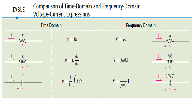
Resistor :
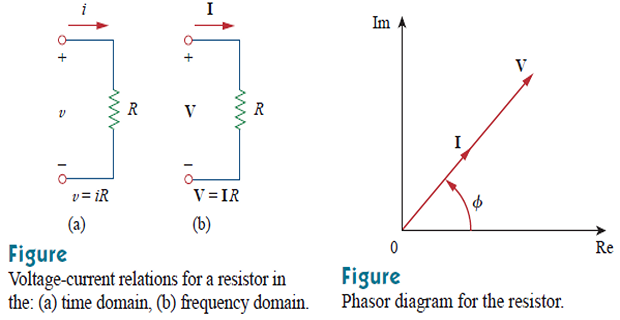 \[\begin{aligned} i &=I_{m} \cos (\omega t+\phi) \quad \Rightarrow \mathbf{I}=I_{m} \angle \phi \\ v &=i R=R I_{m} \cos (\omega t+\phi) \\ \mathbf{V} &=R I_{m} \angle \phi \\ &\boxed{\mathbf{V} =R \mathbf{I}} \end{aligned}\]
Voltage and current are in phase
Inductor :
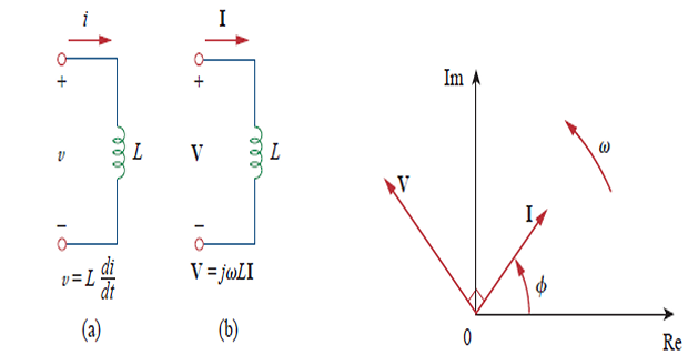 \[\begin{gathered} v=L \frac{d i}{d t}=-\omega L I_{m} \sin (\omega t+\phi) \\ v=\omega L I_{m} \cos \left(\omega t+\phi+90^{\circ}\right) \\ \mathbf{V}=\omega L I_{m} e^{j\left(\phi+90^{\circ}\right)}=\omega L I_{m} e^{j \phi} e^{j 90^{\circ}}=\omega L I_{m} \angle \phi+90^{\circ} \\ \boxed{\mathbf{V}=j \omega L \mathbf{I}} \quad e^{j 90^{\circ}}=j . \end{gathered}\]
Voltage and current are \(90^{\circ}\) out of phase, \(I\) lags \(V\) by \(90^{\circ}\)
- \[\begin{aligned} i & = C \dfrac{dv}{dt} \\ I & = j\omega C V \Rightarrow \boxed{V = \dfrac{I}{j\omega C}} \end{aligned}\]
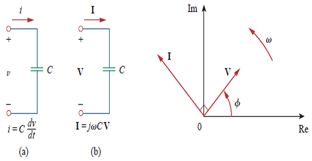
Voltage and current are \(90^{\circ}\) out of phase, \(I\) leads \(V\) by \(90^{\circ}\)
SECTION 01
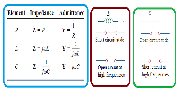
Summary of Relationship
SECTION 01
Impedance & Admittance
- The ratio of phasor voltage to phasor current\[\frac{\mathbf{V}}{\mathbf{I}}=R, \quad \frac{\mathbf{V}}{\mathbf{I}}=j \omega L, \quad \frac{\mathbf{V}}{\mathbf{I}}=\frac{1}{j \omega C}\]
- frequency-dependent quantity) Impedance (in where Ohm’s Law in phasor form\[\boxed{\mathbf{Z} = \dfrac{\mathbf{V}}{\mathbf{I}} \Rightarrow \mathbf{V = ZI}}\]
The impedance \(\mathbf{Z}\) of a circuit is the ratio of the phasor voltage \(\mathbf{V}\) to the phasor current \(\mathbf{I}\), measured in ohms \((\Omega)\).
\(\mathbf{Z}\) : opposition that the circuit exhibits to the flow of sinusoidal current
Although \(\mathbf{Z}\) is the ratio of two phasors, it is not a phasor, because it does not correspond to a sinusoidally varying quantity.
\[\begin{gathered}
\boxed{\mathbf{Z}=R+j X=|\mathbf{Z}| \angle \theta } \quad
|\mathbf{Z}|=\sqrt{R^{2}+X^{2}}, \quad \theta=\tan ^{-1} \frac{X}{R}
\\
\boxed{R=|\mathbf{Z}| \cos \theta} \quad \boxed{X=|\mathbf{Z}| \sin
\theta} \\
\boxed{\mathbf{Y}=\frac{1}{\mathbf{Z}}=\frac{\mathbf{I}}{\mathbf{V}}
}\\
\mathbf{Y}=G+j B \quad \left(G: \text{Conductance}~B:
\text{Susceptance}\right) \\
G+j B=\frac{1}{R+j X}
\end{gathered}\]
\[\boxed{G=\frac{R}{R^{2}+X^{2}}} \quad
\boxed{B=-\frac{X}{R^{2}+X^{2}}}\]