- Compute the capacitance of a parallel-plate capacitor from its geometry and dielectric.
- Relate capacitor current and voltage by differentiation and integration, and compute the stored energy.
- Combine capacitors in series and parallel, and apply the capacitive divider.
- State Faraday's law as it applies to an inductor and use \(v = L\,di/dt\) in both directions.
- Combine inductors in series and parallel, noting the contrast with capacitors.
- Explain the duality between the two elements and use it to halve what must be memorised.
- Replace capacitors and inductors by open and short circuits under DC steady-state conditions.
- State the continuity conditions and explain why they matter for switching circuits.
- Analyse the op-amp integrator and differentiator.
Introduction
Everything in Part 1 so far has been resistive. A resistor converts electrical energy irreversibly into heat, and the energy is gone; its voltage and current are related by a simple proportionality, so the circuit responds instantaneously and the equations are algebraic.
This chapter introduces two elements that behave quite differently. The capacitor stores energy in an electric field, and the inductor stores energy in a magnetic field. Both are passive — they cannot generate energy, and only what has been put in can be taken out — but neither dissipates. Energy flows in, waits, and later flows back out.
That storage has a profound consequence. Because energy takes time to accumulate, the present behaviour of such a circuit depends on its past. A circuit containing these elements has memory, its describing equations become differential rather than algebraic, and its response takes time to settle. Chapters 7 and 8 are devoted to solving those equations; this chapter establishes the elements themselves.
There is a deeper framework behind all of this. Electromagnetic field theory, through Maxwell's equations, is the fundamental description of electrical phenomena; circuit theory is a drastic but extremely effective simplification of it. Capacitance is the circuit property that accounts for energy stored in electric fields, and inductance the property that accounts for energy stored in magnetic fields. Chapter 13 adds mutual inductance, which accounts for magnetic fields shared between coils and forms the basis of the transformer.
Capacitors
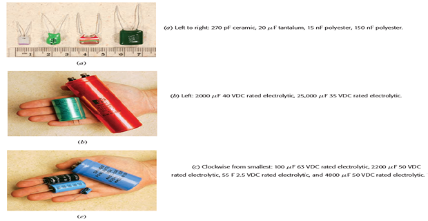
A capacitor is a passive element designed to store energy in its electric field. It is made by separating two conducting sheets with a thin layer of insulating material called a dielectric — air, polyester, polypropylene, mica, ceramic or an electrolytic oxide layer.
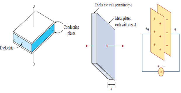
When a voltage source is connected, it drives charge onto one plate and removes an equal amount from the other. In an ideal capacitor the stored charge is directly proportional to the voltage between the plates:
The constant of proportionality \(C\) is the capacitance, measured in farads (F), equivalent to coulombs per volt. The farad is an enormous unit; practical capacitors range from picofarads to millifarads, with only supercapacitors reaching whole farads.
A point that confuses many students: the total charge on the capacitor is always zero. The positive charge on one plate is exactly balanced by negative charge on the other. What we call "the charge stored" is the magnitude on one plate, not a net accumulation.
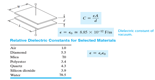
For plates of area \(A\) separated by a distance \(d\), with a dielectric of permittivity \(\varepsilon\) between them,
where \(\varepsilon = \varepsilon_{r}\varepsilon_{0}\), with \(\varepsilon_{0} = 8.854\times10^{-12}~\mathrm{F/m}\) the permittivity of free space and \(\varepsilon_{r}\) the relative permittivity — the dielectric constant — of the material.
Three ways to increase capacitance follow directly: enlarge the plate area, reduce the separation, or choose a dielectric of higher permittivity. This is why practical capacitors are made from long strips of metallised film rolled into a cylinder: the roll packs an enormous area into a small volume.
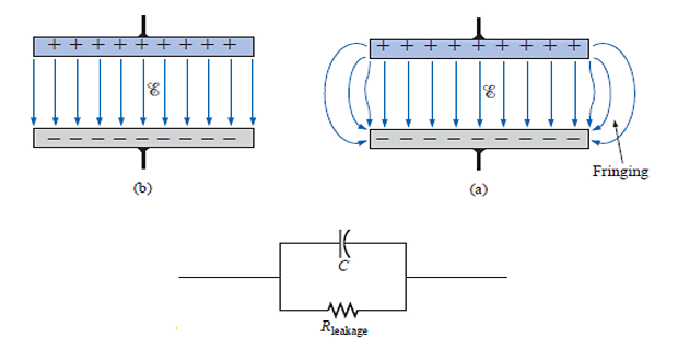
The formula assumes the field is uniform and entirely confined between the plates. In reality it bulges outward at the edges — fringing — so the true capacitance is slightly larger than calculated. For plates whose dimensions are large compared with their separation the error is small.
An analogy helps here, provided its limits are understood. Picture the capacitor as a reservoir divided by an elastic membrane, with fluid entering one side and leaving the other.
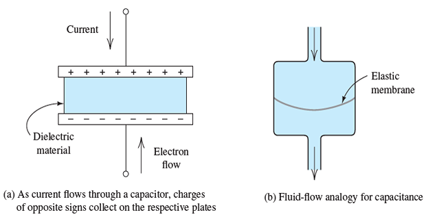
As fluid flows in, the membrane stretches, and the pressure difference across it rises. Fluid appears to flow through the device even though no molecule crosses the membrane. Eventually the membrane is stretched so far that flow ceases.
The electrical picture is exactly parallel. Electrons accumulate on one plate, producing an electric field in the dielectric that pushes an equal number off the other plate at the same rate. Current therefore appears to flow through the capacitor, though no charge crosses the insulator. As charge accumulates, the voltage rises, opposing further accumulation — and under a steady voltage the current stops entirely.
Problem. A capacitor has plates of area \(100~\mathrm{cm^{2}}\) separated by \(0.1~\mathrm{mm}\) of a dielectric with \(\varepsilon_{r} = 4\). Find its capacitance, and the charge and energy stored when 50 V is applied.
Solution. Convert to SI units before anything else — this is where most errors occur:
The stored charge and energy at 50 V:
Note the scale. A hundred square centimetres of plate — a substantial physical object — yields only a few nanofarads, and a few microjoules of energy. This is why capacitors of any appreciable value need rolled or etched construction.
Capacitor Relations and Energy
Current is the time rate of flow of charge, so differentiating \(q = Cv\) gives the capacitor's defining relation. Since capacitance is a constant, not a function of time,
This one equation carries the whole character of the element. The current depends not on the voltage but on its rate of change. A rapidly changing voltage produces a large current; a constant voltage produces none at all, however large that voltage may be.
As with every relation in this book, it assumes the passive sign convention of Chapter 1: current entering the terminal marked positive.
Turning the relation round requires integration. Starting from \(i = C\,dv/dt\) and integrating from a reference time \(t_{0}\) to the present:
The term \(v(t_{0})\) is the initial condition — the voltage already present when we started watching. It is not optional, and forgetting it is one of the most common errors in transient analysis. It is precisely the circuit's memory of everything that happened before \(t_{0}\), compressed into a single number.
Take a capacitor that is initially uncharged, so \(v(t_{0}) = 0\). The instantaneous power delivered to it is
Integrating power over time gives energy. The substitution that makes this work is to change the variable of integration from time to voltage, since \((dv/dt)\,dt = dv\):
All three forms are equivalent, related through \(q = Cv\); use whichever matches what you know. Note that the energy depends on the square of the voltage, so it is always positive regardless of polarity — a capacitor charged to \(-100\) V stores exactly as much energy as one charged to \(+100\) V.
A capacitor is an open circuit to DC. If the voltage is not changing, \(dv/dt = 0\) and so \(i = 0\). This does not mean a battery cannot charge a capacitor — it means that once charged, no further current flows.
The voltage across a capacitor cannot change abruptly. An instantaneous jump would require an infinite \(dv/dt\) and therefore infinite current, which no real source can supply. This continuity condition is the foundation of Chapter 7:
\[v_{C}(0^{+}) = v_{C}(0^{-})\]The current, by contrast, may jump discontinuously and frequently does.
An ideal capacitor dissipates no energy. It absorbs power while charging and returns it while discharging. Over a complete cycle the net energy consumed is zero.
A real capacitor leaks. No dielectric is a perfect insulator, so a real device is modelled as an ideal capacitor with a large parallel leakage resistance — often \(100~\mathrm{M}\Omega\) or more. It is negligible in most applications, but it is why a charged capacitor eventually discharges itself on the shelf.
Problem. The voltage across a \(5~\mu\mathrm{F}\) capacitor is \(v = 10\cos 2000t~\mathrm{V}\). Find the current, its peak value, and its value at \(t = 0.5~\mathrm{ms}\).
Solution. Differentiate and multiply by the capacitance:
The peak current is therefore 100 mA. At \(t = 0.5~\mathrm{ms}\) the argument is \(2000(0.5\times10^{-3}) = 1~\mathrm{rad}\), and \(\sin 1 = 0.8415\):
Two observations. The current is a sine where the voltage was a cosine, so the current leads the voltage by 90° — a fact that becomes central in Chapter 9. And the peak current rises in proportion to frequency: at 20 000 rad/s the same voltage would drive a full ampere. A capacitor passes high frequencies far more readily than low ones.
Problem. A \(20~\mu\mathrm{F}\) capacitor, initially uncharged, is fed a constant current of 100 mA for 3 ms, after which the current is switched off. Find the voltage at \(t = 3~\mathrm{ms}\), the voltage afterwards, and the energy stored.
Solution. With a constant current the integral is simply a product:
After the current is switched off, \(i = 0\) means \(dv/dt = 0\), so the voltage remains at 15 V indefinitely — the capacitor holds its charge. This is the clearest possible demonstration of memory: the element retains a record of the current that flowed through it long after that current has ceased.
In a real capacitor the leakage resistance would slowly discharge it, but over seconds or minutes the ideal picture is accurate. It is also a genuine hazard: large capacitors in power equipment can hold a lethal charge long after the supply is disconnected, which is why such equipment carries bleeder resistors and discharge warnings.
Problem. A current \(i = 6e^{-3000t}~\mathrm{mA}\) flows into an uncharged \(0.1~\mu\mathrm{F}\) capacitor. Find \(v(t)\), its value at \(t = 0.5~\mathrm{ms}\), and its final value.
Solution.
The integral of the exponential is
At \(t = 0.5~\mathrm{ms}\) the exponent is \(-1.5\), and \(e^{-1.5} = 0.2231\):
As \(t \to \infty\) the exponential vanishes and \(v \to 20~\mathrm{V}\). Check by charge. The total charge delivered is the area under the current curve, \(6\times10^{-3}/3000 = 2~\mu\mathrm{C}\), and the final voltage should be \(q/C = 2\times10^{-6}/0.1\times10^{-6} = 20~\mathrm{V}\) \(\checkmark\). The rising-exponential shape is exactly the charging curve that Chapter 7 derives from first principles.
Series and Parallel Capacitors
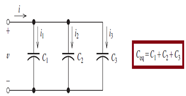
Parallel elements share the same voltage. Each capacitor therefore carries its own current, determined by the common \(dv/dt\):
Applying KCL at the top node:
Capacitances in parallel add. This is physically obvious from the parallel-plate formula: connecting capacitors in parallel is equivalent to enlarging the plate area, and \(C \propto A\).
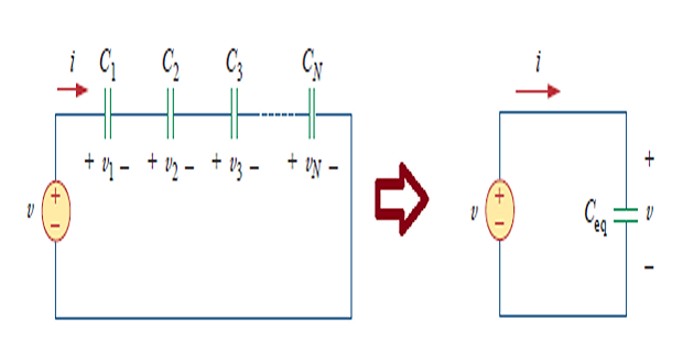
Series elements share the same current. The voltages therefore add:
and each individual voltage is given by the integral relation:
Substituting and collecting the common integral:
Capacitances in series combine as reciprocals. For two in series the product-over-sum shortcut applies, exactly as for parallel resistors:
Note the reversal carefully. Capacitors combine in the opposite way to resistors: series capacitors follow the reciprocal rule that parallel resistors obey, and parallel capacitors simply add as series resistors do. This is not a coincidence — it is the duality explored in Section 6.8 — but until that becomes second nature it is a reliable source of errors.
Series capacitors all carry the same current, so they all accumulate the same charge \(Q\). Since \(v_{k} = Q/C_{k}\), the voltage across each is inversely proportional to its capacitance. For two in series:
The other capacitance appears in the numerator — the same crossover as the current divider of Section 2.8, and the opposite of the voltage divider. The consequence is worth stating plainly: the smaller capacitor takes the larger share of the voltage. A quick sanity check that never fails.
Problem. (a) Find \(C_{\mathrm{eq}}\) for a \(60~\mu\mathrm{F}\) in series with a \(20~\mu\mathrm{F}\), that combination in parallel with a \(5~\mu\mathrm{F}\), and the whole in series with a \(30~\mu\mathrm{F}\). (b) A 30 V source is applied across a \(6~\mu\mathrm{F}\) in series with a \(3~\mu\mathrm{F}\). Find the voltage across each.
Solution (a). Work from the inside out, as in Chapter 2:
Solution (b). First the equivalent and the common charge:
Both capacitors carry this same charge, so
KVL confirms \(10 + 20 = 30\) V \(\checkmark\). By the divider formula, \(v_{6\mu\mathrm{F}} = \frac{3}{9}(30) = 10\) V \(\checkmark\). The smaller capacitor takes twice the voltage — the reverse of what a resistive divider would do, and the reason series capacitors in high-voltage equipment need balancing resistors.
Inductors
An inductor is a passive element designed to store energy in its magnetic field. In its simplest form it is a coil of conducting wire, sometimes wound on a core of magnetic material.
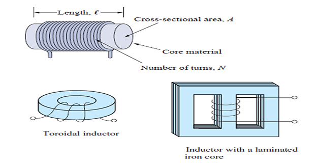
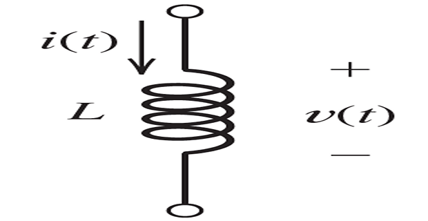
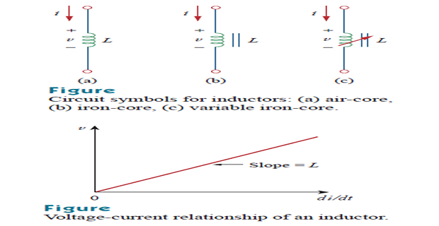
Current flowing in the coil produces a magnetic flux \(\Phi\) that links the turns. When the current changes, so does the flux, and by Faraday's law of electromagnetic induction a time-varying flux linking a coil induces a voltage across it. For an ideal inductor that voltage is proportional to the rate of change of current:
The constant of proportionality \(L\) is the inductance, measured in henries (H), equivalent to volt-seconds per ampere. Practical values run from microhenries in radio circuits to henries in power-supply chokes.
The polarity matters and is not arbitrary. By Lenz's law, the induced voltage opposes the change in current that produced it. An inductor resists any attempt to alter the current through it — which is precisely why the current cannot change instantaneously.
For a coil of \(N\) turns wound on a core of permeability \(\mu\), cross-sectional area \(A\) and length \(\ell\),
Inductance rises with the square of the turns, so doubling the winding quadruples the inductance. It can also be increased by using a core of higher permeability, enlarging the cross-section, or shortening the coil.
Where the capacitor was a stretched membrane, the inductor is inertia. Picture fluid flowing through a frictionless pipe of constant diameter: pressure difference corresponds to voltage, flow rate to current, and acceleration of the fluid to \(di/dt\).
A pressure difference exists between the ends of the pipe only when the flow is speeding up or slowing down. Steady flow needs no pressure difference at all — just as steady current needs no voltage across an ideal inductor.
The analogy also explains a familiar and violent phenomenon. Close a valve suddenly on a pipe carrying fast-moving water and the inertia of the fluid produces a large pressure surge — water hammer, which can burst the pipe. Open a switch suddenly in a circuit carrying inductor current and the same thing happens electrically: \(di/dt\) becomes enormous, and so does the induced voltage, producing an arc across the switch contacts. This is the mechanism behind ignition coils, and behind the destruction of switches that were not designed for inductive loads.
Inductor Relations and Energy
Inverting the defining relation requires integration, exactly as for the capacitor:
Again the initial condition \(i(t_{0})\) carries the memory of the past, and again it must not be dropped.
This relation also proves the continuity condition. So long as the voltage \(v(t)\) remains finite, the integral over an infinitesimal interval is infinitesimal, so the current can change only by an infinitesimal amount in an infinitesimal time. The inductor current must therefore be continuous, with no instantaneous jumps:
The voltage, by contrast, may jump freely and usually does.
The derivation runs exactly parallel to the capacitor case, with current in place of voltage:
This energy is stored in the magnetic field and returned to the circuit if the current falls back to zero. As with the capacitor it depends on a square, so it is always positive — the direction of current is irrelevant.
An inductor is a short circuit to DC. If the current is not changing, \(di/dt = 0\) and so \(v = 0\). A steady current passes through with no voltage drop at all — in an ideal inductor, of any magnitude.
The current through an inductor cannot change abruptly. A jump would require infinite \(di/dt\) and therefore infinite voltage.
An ideal inductor dissipates no energy. It stores and returns.
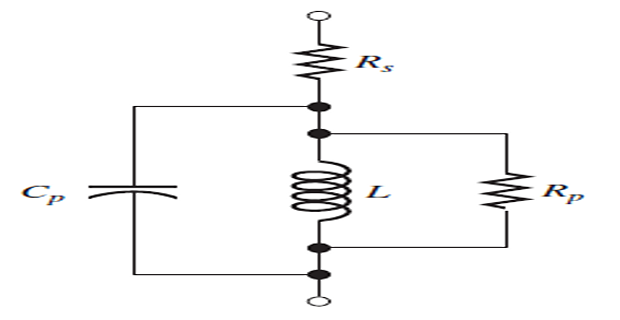
A real inductor has parasitic effects. Three of them, each with a physical origin: a series resistance \(R_{s}\) from the resistivity of the winding wire; an inter-winding capacitance from the electric field in the insulation between adjacent turns; and a parallel resistance \(R_{p}\) representing core losses. The series resistance is usually the one that matters, and it is why a real inductor is a far poorer approximation to the ideal than a real capacitor.
Problem. The current through a 5 mH inductor is \(i = 2\sin 377t~\mathrm{A}\). Find the voltage, and the energy stored at \(t = 5~\mathrm{ms}\).
Solution.
At \(t = 5~\mathrm{ms}\) the argument is \(377(5\times10^{-3}) = 1.885~\mathrm{rad}\), so \(\sin 1.885 = 0.9511\) and \(\cos 1.885 = -0.3090\):
The voltage is a cosine where the current was a sine, so here the voltage leads the current by 90° — the exact opposite of the capacitor in Example 6.2. That opposition is what makes resonance possible, and Chapter 14 is built on it. Note also that 377 rad/s is \(2\pi \times 60\), the mains frequency in North America.
Problem. A 3 H inductor carrying an initial current of 1 A has 12 V applied across it for 2 s, after which the voltage is removed (the inductor is short-circuited). Find the current at \(t = 2~\mathrm{s}\), the current afterwards, and the stored energy.
Solution. With a constant voltage the integral is a product:
Once the inductor is short-circuited, \(v = 0\) gives \(di/dt = 0\), so the current remains at 9 A indefinitely — the dual of the capacitor holding its voltage in Example 6.3. In a real inductor the winding resistance would decay it; in a superconducting magnet, which genuinely has zero resistance, persistent currents do circulate for years.
Compare this with the 2.25 mJ of Example 6.3. Inductors store far more energy for a given physical size than capacitors do — which is why energy-storage chokes are used in switched-mode power supplies, and why opening the circuit of a large inductor is genuinely dangerous.
Series and Parallel Inductors
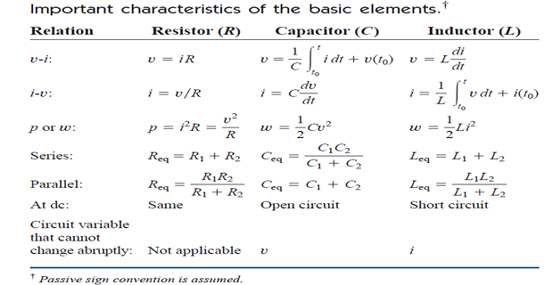
Inductors combine in exactly the same way as resistors — which, since capacitors were the reverse, means half the memorisation is already done.
Series. The same current flows through all of them, so the voltages add:
Parallel. The same voltage appears across all of them, so the currents add:
For two in parallel the product-over-sum shortcut applies as usual.
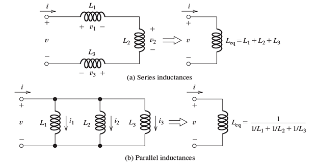
One caution. These rules assume the inductors are magnetically isolated — that the flux of one does not link the turns of another. Coils mounted close together violate this, and their combination involves the mutual inductance of Chapter 13.
Problem. A 4 H and an 8 H inductor are in series; that combination is in parallel with a 6 H; and the result is in series with a 2 H. Find \(L_{\mathrm{eq}}\).
Solution. As always, work from the inside out:
Note that the parallel result, 4 H, is smaller than either 12 H or 6 H — the same behaviour as parallel resistors, and worth using as a check.
Duality and DC Steady State
Look back over the last six sections and a pattern is unmistakable. Every statement about the capacitor has a mirror-image statement about the inductor, obtained by exchanging \(v \leftrightarrow i\) and \(C \leftrightarrow L\). This is duality, and it is not a coincidence but a deep structural property of circuit theory.
| Property | Capacitor | Inductor |
|---|---|---|
| Stores energy in | electric field | magnetic field |
| Defining relation | \(i = C\dfrac{dv}{dt}\) | \(v = L\dfrac{di}{dt}\) |
| Integral relation | \(v = \dfrac{1}{C}\displaystyle\int i\,dt + v(t_0)\) | \(i = \dfrac{1}{L}\displaystyle\int v\,dt + i(t_0)\) |
| Stored energy | \(w = \tfrac{1}{2}Cv^{2}\) | \(w = \tfrac{1}{2}Li^{2}\) |
| Cannot change abruptly | voltage | current |
| At DC behaves as | open circuit | short circuit |
| In series | reciprocals add | values add |
| In parallel | values add | reciprocals add |
| Principal parasitic | parallel leakage \(R\) | series winding \(R\) |
Learn one column properly and the other follows by translation. Duality reappears formally in Chapter 8, where the dual of a network is constructed systematically, and informally throughout the rest of the book.
One consequence of duality is immediately useful and worth isolating. When a circuit has been connected to DC sources for a long time, all transients have died away and nothing is changing any more. In that DC steady state:
Every capacitor has \(dv/dt = 0\), so \(i_{C} = 0\): replace each capacitor by an open circuit.
Every inductor has \(di/dt = 0\), so \(v_{L} = 0\): replace each inductor by a short circuit.
With these substitutions the circuit becomes purely resistive, and every technique from Chapters 2 to 4 applies unchanged. The capacitor voltages and inductor currents found this way are also exactly the initial conditions needed to start a transient analysis when a switch is subsequently thrown — which is how Chapters 7 and 8 begin almost every problem.
Problem. A 24 V source is connected through a 4 \(\Omega\) resistor to node \(A\). A \(2~\mu\mathrm{F}\) capacitor runs from \(A\) to ground, and a 4 H inductor in series with an 8 \(\Omega\) resistor also runs from \(A\) to ground. The circuit has been connected for a long time. Find the capacitor voltage, the inductor current, and the energy stored in each.
Solution. Replace the capacitor by an open circuit and the inductor by a short. What remains is a series circuit of 4 \(\Omega\) and 8 \(\Omega\) across 24 V:
This is the inductor current, since the whole of it flows through that branch. The capacitor voltage is the node voltage at \(A\), which is the drop across the 8 \(\Omega\):
Check by KVL round the loop: \(24 - 2(4) - 16 = 0\) \(\checkmark\). The stored energies:
The inductor stores more than thirty thousand times as much energy as the capacitor here — a reminder of the very different scales these two elements occupy in practice. Note too that the capacitor carries no current and the inductor has no voltage across it; both are invisible to the DC solution, and they matter only when something changes.
Applications: The Integrator and Differentiator
Chapter 5 showed that an op amp with resistive feedback produces a gain fixed by a ratio of resistances. Replace one of those resistors by a capacitor and the circuit performs calculus instead of multiplication. These are the circuits that gave the operational amplifier its name.
Take the inverting amplifier of Section 5.4 and replace the feedback resistor with a capacitor. The two golden rules still apply: the inverting node is a virtual ground at 0 V, and no current enters the amplifier.
The current through the input resistor is
All of it must flow into the capacitor. The capacitor's voltage is \(0 - v_{o} = -v_{o}\), so
Equating the two currents and integrating:
The output is the running integral of the input, scaled by \(1/RC\) and inverted.
A practical warning. A constant input produces a steadily ramping output, which will eventually reach a supply rail and saturate — the check from Section 5.2 is not optional here. Worse, any small DC offset at the input integrates without limit, so a real integrator needs a large resistor in parallel with the capacitor to bleed away the accumulated charge and set a limit on the DC gain.
Exchange the two components instead — capacitor at the input, resistor in the feedback path — and the operation reverses:
The differentiator is far less used than the integrator, for a good reason. Differentiation amplifies rapid changes, and the most rapid changes in any real signal are usually noise. A differentiator therefore emphasises exactly what you want to suppress, and practical designs add a small series resistor to limit the high-frequency gain.
Problem. An integrator has \(R = 100~\mathrm{k}\Omega\) and \(C = 1~\mu\mathrm{F}\), on \(\pm12~\mathrm{V}\) supplies, with the capacitor initially uncharged. A constant 5 V is applied at \(t = 0\). Find \(v_{o}(t)\) and the time at which the amplifier saturates.
Solution. First the time constant of the integrator:
A constant input produces a linear ramp, falling at 50 volts per second. It reaches the negative rail when
After 240 ms the output sticks at \(-12\) V and the integration stops. This is the standard way of generating a linear ramp or sawtooth — and the reason such generators must be reset before saturation is reached.
Summing amplifiers, integrators and inverting amplifiers can be interconnected to solve differential equations directly. To solve \(\ddot{y} + a\dot{y} + by = f(t)\), rearrange it as \(\ddot{y} = f(t) - a\dot{y} - by\), form the right-hand side with a summing amplifier, then integrate twice to obtain \(\dot{y}\) and \(y\), feeding both back to the summer. The machine settles into a voltage waveform that is the solution.
Analogue computers were the standard tool for simulating aircraft dynamics and control systems until digital machines displaced them in the 1970s. The idea survives: the block diagrams of control theory are direct descendants, and the same integrator appears in every analogue filter and switched-mode regulator.
Summary and Key Formulas
Capacitors and inductors store energy rather than dissipating it. Both are passive: only energy previously supplied can be recovered.
A capacitor stores energy in an electric field, with \(q = Cv\) and \(C = \varepsilon A/d\) for parallel plates.
The capacitor relations are \(i = C\,dv/dt\) and its integral inverse, with stored energy \(\tfrac{1}{2}Cv^{2}\).
An inductor stores energy in a magnetic field, with \(v = L\,di/dt\) and stored energy \(\tfrac{1}{2}Li^{2}\).
Capacitors add in parallel and combine reciprocally in series; inductors do the reverse, following the same rules as resistors.
In a capacitive divider the smaller capacitor takes the larger voltage — the opposite of a resistive divider.
Capacitor voltage and inductor current are continuous: neither can change instantaneously.
In DC steady state a capacitor is an open circuit and an inductor a short circuit.
The two elements are duals under \(v \leftrightarrow i\) and \(C \leftrightarrow L\).
An op amp with a feedback capacitor integrates; with an input capacitor it differentiates.
| Quantity | Formula | Notes |
|---|---|---|
| Stored charge | \(q = Cv\) | net charge is zero |
| Parallel-plate capacitance | \(C = \dfrac{\varepsilon_r \varepsilon_0 A}{d}\) | \(\varepsilon_0 = 8.854\times10^{-12}\) F/m |
| Capacitor current | \(i = C\dfrac{dv}{dt}\) | zero for DC |
| Capacitor voltage | \(v = \dfrac{1}{C}\displaystyle\int_{t_0}^{t} i\,dt + v(t_0)\) | initial condition required |
| Capacitor energy | \(w = \tfrac{1}{2}Cv^{2} = \dfrac{q^{2}}{2C}\) | always positive |
| Capacitors in parallel | \(C_{\mathrm{eq}} = \sum C_k\) | add |
| Capacitors in series | \(\dfrac{1}{C_{\mathrm{eq}}} = \sum \dfrac{1}{C_k}\) | reciprocals add |
| Capacitive divider | \(v_1 = \dfrac{C_2}{C_1+C_2}\,v\) | other capacitance on top |
| Inductance of a coil | \(L = \dfrac{N^{2}\mu A}{\ell}\) | square of turns |
| Inductor voltage | \(v = L\dfrac{di}{dt}\) | zero for DC |
| Inductor current | \(i = \dfrac{1}{L}\displaystyle\int_{t_0}^{t} v\,dt + i(t_0)\) | initial condition required |
| Inductor energy | \(w = \tfrac{1}{2}Li^{2}\) | always positive |
| Inductors in series | \(L_{\mathrm{eq}} = \sum L_k\) | as resistors |
| Inductors in parallel | \(\dfrac{1}{L_{\mathrm{eq}}} = \sum \dfrac{1}{L_k}\) | as resistors |
| Continuity | \(v_C(0^{+}) = v_C(0^{-})\), \(i_L(0^{+}) = i_L(0^{-})\) | basis of Chapter 7 |
| Integrator | \(v_o = -\dfrac{1}{RC}\displaystyle\int v_i\,dt\) | check saturation |
| Differentiator | \(v_o = -RC\dfrac{dv_i}{dt}\) | amplifies noise |
Common Mistakes
Combining capacitors as though they were resistors. The rules are reversed. Series capacitors take the reciprocal formula; parallel capacitors simply add. Inductors, by contrast, do behave exactly like resistors.
Omitting the initial condition in an integral relation. The terms \(v(t_{0})\) and \(i(t_{0})\) are the element's memory. Dropping them silently assumes the element started empty.
Assuming capacitor current is continuous, or inductor voltage is. It is capacitor voltage and inductor current that cannot jump. Their partners jump routinely.
Using the DC replacements during a transient. "Capacitor equals open circuit" holds only after everything has settled. During switching it is precisely wrong.
Putting the wrong capacitance on top in a capacitive divider. Check against the physics: the smaller capacitor must take the larger voltage.
Forgetting to square the length conversion for plate area. \(100~\mathrm{cm^{2}}\) is \(10^{-2}~\mathrm{m^{2}}\), not \(1~\mathrm{m^{2}}\).
Treating \(N\) as linear in the inductance formula. Inductance goes as \(N^{2}\), so doubling the turns quadruples it.
Assuming series or parallel inductor formulas apply to coupled coils. They hold only when there is no mutual flux; otherwise Chapter 13's treatment is needed.
Ignoring saturation in an integrator. A constant input ramps the output until it hits a rail. Always check when.
Believing a disconnected capacitor is safe. A large capacitor holds its charge for a long time after the supply is removed, and the stored energy can be lethal.
Chapter Review
Work these before opening the answers. Quote results to four significant figures with correct units.
P6.1 An air-dielectric capacitor has plates of area \(4~\mathrm{cm^{2}}\) separated by \(0.02~\mathrm{mm}\). Find its capacitance.
Show answer
With \(\varepsilon_r = 1\) for air:\[C = \frac{\left(8.854\times10^{-12}\right)\left(4\times10^{-4}\right)}{2\times10^{-5}} = 1.771\times10^{-10}~\mathrm{F} = 177.1~\mathrm{pF}\]P6.2 The voltage across a \(2~\mu\mathrm{F}\) capacitor is \(v = 20\cos 1000t~\mathrm{V}\). Find the current and its peak value.
Show answer
The peak current is 40.00 mA.\[i = C\frac{dv}{dt} = \left(2\times10^{-6}\right)\left(-20\,000\sin 1000t\right) = -0.04\sin 1000t~\mathrm{A}\]P6.3 A \(5~\mu\mathrm{F}\) capacitor is charged to 100 V. Find the stored charge and energy.
Show answer
\[q = Cv = \left(5\times10^{-6}\right)(100) = 500~\mu\mathrm{C}\]\[w = \tfrac{1}{2}Cv^{2} = \tfrac{1}{2}\left(5\times10^{-6}\right)\left(10^{4}\right) = 25.00~\mathrm{mJ}\]P6.4 Find the equivalent capacitance of \(4~\mu\mathrm{F}\), \(6~\mu\mathrm{F}\) and \(12~\mu\mathrm{F}\) in series.
Show answer
\[\frac{1}{C_{\mathrm{eq}}} = \frac{1}{4}+\frac{1}{6}+\frac{1}{12} = \frac{3+2+1}{12} = \frac{6}{12} = \frac{1}{2}\]Smaller than the smallest, as series capacitors must be.\[C_{\mathrm{eq}} = 2.000~\mu\mathrm{F}\]P6.5 A 100 V source is applied across a \(2~\mu\mathrm{F}\) in series with an \(8~\mu\mathrm{F}\). Find the voltage across each.
Show answer
\[C_{\mathrm{eq}} = \frac{(2)(8)}{10} = 1.6~\mu\mathrm{F}, \qquad Q = \left(1.6\times10^{-6}\right)(100) = 160~\mu\mathrm{C}\]Sum is 100 V \(\checkmark\). The smaller capacitor takes four times the voltage.\[v_{2\mu\mathrm{F}} = \frac{160}{2} = 80.00~\mathrm{V}, \qquad v_{8\mu\mathrm{F}} = \frac{160}{8} = 20.00~\mathrm{V}\]P6.6 A current \(i = 4t~\mathrm{A}\) flows through a 200 mH inductor. Find the voltage, and the energy stored at \(t = 3~\mathrm{s}\).
Show answer
\[v = L\frac{di}{dt} = (0.2)(4) = 0.8000~\mathrm{V} \quad\text{(constant)}\]A linearly rising current produces a constant voltage — the dual of a constant current producing a linearly rising voltage on a capacitor.\[i(3) = 12~\mathrm{A}, \qquad w = \tfrac{1}{2}(0.2)(144) = 14.40~\mathrm{J}\]P6.7 A 2 H and a 6 H inductor are in series, and that combination is in parallel with an 8 H. Find \(L_{\mathrm{eq}}\).
Show answer
\[2 + 6 = 8~\mathrm{H}, \qquad L_{\mathrm{eq}} = \frac{(8)(8)}{16} = 4.000~\mathrm{H}\]P6.8 A 20 V source feeds a 5 \(\Omega\) resistor in series with a 15 \(\Omega\) resistor. A capacitor is connected across the 15 \(\Omega\), and an inductor is in series with the 15 \(\Omega\). After a long time, find the inductor current and the capacitor voltage.
Show answer
Capacitor becomes an open circuit, inductor a short:\[i_L = \frac{20}{5+15} = 1.000~\mathrm{A}, \qquad v_C = (1)(15) = 15.00~\mathrm{V}\]P6.9 An integrator has \(R = 50~\mathrm{k}\Omega\) and \(C = 2~\mu\mathrm{F}\), initially uncharged. A constant \(-2~\mathrm{V}\) is applied. Find \(v_{o}(t)\) and the time to reach 10 V.
Show answer
\[RC = \left(50\times10^{3}\right)\left(2\times10^{-6}\right) = 0.1~\mathrm{s}\]\[v_o = -\frac{1}{0.1}\int_0^t (-2)\,dt = +20t~\mathrm{V}\]A negative input gives a positive-going ramp.\[20t = 10 \;\Longrightarrow\; t = 0.5000~\mathrm{s}\]P6.10 A 10 mH inductor carries 5 A when a switch is opened, interrupting the current in \(1~\mu\mathrm{s}\). Estimate the average induced voltage, and comment.
Show answer
The stored energy is \(\tfrac{1}{2}(10\times10^{-3})(25) = 125.0~\mathrm{mJ}\), and it must go somewhere in that microsecond. In practice an arc strikes across the opening contacts and dissipates it. This is why inductive loads need a freewheeling diode or snubber, and why the same effect is exploited deliberately in an ignition coil.\[v = L\frac{\Delta i}{\Delta t} = \left(10\times10^{-3}\right)\frac{5}{1\times10^{-6}} = 50\,000~\mathrm{V} = 50.00~\mathrm{kV}\]
MCQ 1. The unit of capacitance is the:
(a) henry (b) farad (c) coulomb (d) siemensShow answer
(b) farad, equivalent to coulombs per volt. The henry is the unit of inductance.MCQ 2. In DC steady state a capacitor behaves as:
(a) a short circuit (b) an open circuit (c) a resistor (d) a sourceShow answer
(b) an open circuit, since \(dv/dt = 0\) forces \(i = 0\). An inductor becomes a short.MCQ 3. Three \(6~\mu\mathrm{F}\) capacitors in series give an equivalent of:
(a) 18 \(\mu\)F (b) 6 \(\mu\)F (c) 2 \(\mu\)F (d) 3 \(\mu\)FShow answer
(c) 2 \(\mu\)F. For \(N\) equal capacitors in series, \(C_{\mathrm{eq}} = C/N\). Option (a) is the parallel answer.MCQ 4. The quantity that cannot change instantaneously is:
(a) capacitor current (b) capacitor voltage (c) inductor voltage (d) resistor voltageShow answer
(b) capacitor voltage — and inductor current. Their partners may jump freely.MCQ 5. The energy stored in a 2 H inductor carrying 3 A is:
(a) 3 J (b) 6 J (c) 9 J (d) 18 JShow answer
(c) 9 J. \(w = \tfrac{1}{2}(2)(9) = 9\) J. Option (d) omits the factor of one half.MCQ 6. Doubling the number of turns on a coil changes its inductance by a factor of:
(a) 2 (b) 4 (c) 1/2 (d) 1/4Show answer
(b) 4, since \(L \propto N^{2}\).MCQ 7. Two capacitors in series across a source. The larger share of the voltage appears across:
(a) the larger capacitor (b) the smaller capacitor (c) both equally (d) it depends on the sourceShow answer
(b) the smaller capacitor. Both carry the same charge, and \(v = Q/C\).MCQ 8. A capacitor of \(4~\mu\mathrm{F}\) in parallel with a \(6~\mu\mathrm{F}\) is equivalent to:
(a) 2.4 \(\mu\)F (b) 10 \(\mu\)F (c) 24 \(\mu\)F (d) 5 \(\mu\)FShow answer
(b) 10 \(\mu\)F. Parallel capacitors add. Option (a) is the series answer.MCQ 9. An op amp with a resistor at the input and a capacitor in the feedback path acts as:
(a) a differentiator (b) an integrator (c) a summer (d) a comparatorShow answer
(b) an integrator. Swapping the two components gives the differentiator.MCQ 10. The principal parasitic element of a real inductor is a:
(a) parallel capacitance (b) series resistance (c) parallel resistance (d) series inductanceShow answer
(b) series resistance, from the resistivity of the winding. A real capacitor's principal parasitic is a parallel leakage resistance — the dual.
Current "flows through" a capacitor even though its plates are separated by an insulator. Explain what is actually happening, and in what sense the statement is true.
Why can the voltage across a capacitor not change instantaneously, while its current can? Give the dual statement for an inductor.
Capacitors combine in series the way resistors combine in parallel. Explain this using the parallel-plate formula rather than the algebra.
An inductor stores 8 J while a capacitor in the same circuit stores 256 \(\mu\)J. What does this suggest about where each element is useful in practice?
The DC replacements — capacitor open, inductor short — are described as valid "after a long time". How long is long enough, and what determines it? (Chapter 7 will answer this precisely; give a qualitative argument now.)
A differentiator is mathematically the exact inverse of an integrator, yet integrators are far more common in practice. Explain why, in terms of what each does to noise.
You now have three elements and their defining relations, but no method for solving a circuit that contains them. Applying KVL to a loop with a resistor and a capacitor produces not an algebraic equation but a differential one, and the tools of Chapters 2 to 4 stop short of solving it.
Chapter 7 supplies that method for circuits containing a single storage element — the first-order RC and RL circuits. Two ideas from this chapter do the essential work: the continuity conditions supply the initial value, and the DC steady-state replacements supply the final value. Between them and a single time constant \(\tau\), every first-order response in existence can be written down without solving anything.
Chapter 8 then takes circuits with two storage elements, where the equation is second order and the response can oscillate — the beginning of resonance, and of everything in Part 2.