Section 1
Introduction to Three-Phase Drives
Why Three-Phase Drives?
Three-phase phase-controlled drives offer significant advantages over their single-phase counterparts, making them the industry standard for medium- to high-power DC motor applications. The key advantages are:
- Higher Power Ratings: Suitable for $100\;\text{kW}$ to $1500\;\text{kW}$ and beyond.
- Higher Ripple Frequency:
- Single-phase full-bridge: ripple at $2f$ (e.g. $120\;\text{Hz}$ for a $60\;\text{Hz}$ supply).
- Three-phase full-bridge (6-pulse): ripple at $6f$ (e.g. $360\;\text{Hz}$ for a $60\;\text{Hz}$ supply).
- Lower Filtering Requirements: Smaller smoothing inductor required for the same current-ripple specification.
- Better Motor Performance: More continuous armature current leads to smoother torque.
- Lower Torque Pulsation: Smoother shaft torque reduces mechanical stress.
- Higher Efficiency: Better utilisation of transformer and supply capacity.
Power Ranges for Different DC Drive Topologies
| Drive Type | Typical Power Range | Applications |
|---|---|---|
| Single-Phase Full-Bridge | Up to $100\;\text{kW}$ | Small drives |
| Three-Phase Semiconverter | Up to $115\;\text{kW}$ | Medium drives |
| Three-Phase Full-Converter | Up to $1500\;\text{kW}$ | Large drives |
| Three-Phase Dual-Converter | Up to $1500\;\text{kW}$ | High-performance drives |
| 12-Pulse (Series/Parallel) | Above $1\;\text{MW}$ | Very large drives |
Industrial Standard
Three-phase phase-controlled drives are the industry standard for medium- to high-power DC-motor applications.Classification of Three-Phase Drives
Based on converter configuration, three-phase drives are classified as follows:
- Three-Phase Half-Wave (3-pulse) Converter: Requires a neutral connection; rarely used industrially.
- Three-Phase Semiconverter (half-controlled bridge): One-quadrant operation (forward motoring only); up to $115\;\text{kW}$.
- Three-Phase Full-Converter (fully-controlled bridge): Two-quadrant operation (motoring + regenerative braking); up to $1500\;\text{kW}$.
- Three-Phase Dual-Converter: Four-quadrant operation; up to $1500\;\text{kW}$.
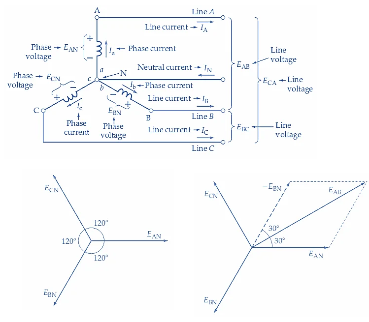
Three-Phase Supply — Notation
The standard three-phase system with phase sequence $a$-$b$-$c$ is described by the phase voltages of a Y-connected supply:
where $V_m = \sqrt{2}\,V_p$ is the peak phase voltage and $V_{Lm} = \sqrt{2}\,V_L = \sqrt{3}\,V_m$ is the peak line-to-line voltage. The fundamental relation is $V_L = \sqrt{3}\,V_p$.
Ripple Frequency Comparison
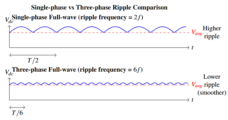
Key Observation:
- Single-phase bridge (2-pulse): ripple period $= T/2$, ripple frequency $= 2f$
- Three-phase bridge (6-pulse): ripple period $= T/6$, ripple frequency $= 6f$
Consequence
A six times higher ripple frequency means the peak-to-peak voltage ripple is much smaller, so a smaller smoothing inductor $L_a$ is needed for the same current-ripple specification.Section 2
Three-Phase Semiconverter Drives
The three-phase semiconverter (half-controlled bridge) is a one-quadrant drive suitable for forward motoring only. It is used for power ranges up to $115\;\text{kW}$ and is less expensive than a full-converter due to a lower device count.
The circuit consists of:
- 3 thyristors forming the positive (controlled) group
- 3 diodes forming the negative (uncontrolled) group
- 1 freewheeling diode $D_F$
The output voltage is always $\geq 0$, which means regenerative braking is not possible.
Field Supply
Typically a single-phase semiconverter or full-converter is used for the field circuit.Limitation
Cannot perform regenerative braking or electronic speed reversal.Circuit Diagram
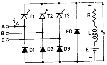
Operating Principle
Positive Group — Thyristors $T_1, T_3, T_5$:
- Each thyristor is fired with a common delay angle $\alpha$ after its respective phase voltage becomes the most positive.
- Provides the high-potential rail of the output.
Negative Group — Diodes $D_4, D_6, D_2$:
- Diodes conduct naturally (no delay) on the most negative phase.
- Provides the low-potential rail.
Freewheeling Diode $D_F$:
- Conducts whenever the instantaneous converter output would go negative.
- Clamps $v_o \geq 0$ and maintains continuous armature current.
- Reduces current ripple and protects the motor from negative voltage transients.
Voltage and Current Waveforms
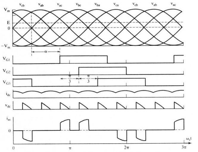
Average Output Voltage
The average armature voltage for a three-phase semiconverter is given by:
Key Equation — Semiconverter
where $V_m = \sqrt{2}\,V_p$ is the peak phase voltage. An equivalent expression in terms of the line voltage $V_L$ is:
since $\sqrt{3}\,V_m = V_{Lm} = \sqrt{2}\,V_L$.
Voltage Range
- $\alpha = 0°$: $\quad V_a = \dfrac{3\sqrt{3}\,V_m}{\pi}$ (maximum; equals the full-converter $V_{a,\max}$)
- $\alpha = 180°$: $\quad V_a = 0$ (minimum)
Advantages and Disadvantages
Advantages:
- Simpler gate-drive logic than full-converter
- Lower device count and cost
- Freewheeling diode reduces current ripple
- Good for constant-speed or unidirectional loads
- Suitable for medium power levels
Disadvantages:
- One-quadrant operation only
- No regenerative braking
- Speed reversal requires mechanical contactors
- Less flexible than a full-converter
Typical Applications
Pumps, fans, conveyors, and other unidirectional loads up to $115\;\text{kW}$ that do not require regeneration.Section 3
Three-Phase Full-Converter Drives
The three-phase full-converter (fully-controlled bridge) is the most widely used three-phase DC-drive topology in industry. It provides two-quadrant operation — forward motoring and forward regenerative braking — and handles power up to $1500\;\text{kW}$.
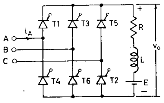
The circuit consists entirely of six thyristors (three in the positive group, three in the negative group) with no diodes in the main power path, allowing bidirectional voltage control.
Quadrant Capability
- Without field reversal: Quadrants I and II (forward motoring + forward regeneration)
- With field reversal: access to all four quadrants
Circuit Diagram
Thyristor Firing and Conduction
The bridge structure consists of:
- Positive group: $T_1$ (phase $a$), $T_3$ (phase $b$), $T_5$ (phase $c$)
- Negative group: $T_4$ (phase $a$), $T_6$ (phase $b$), $T_2$ (phase $c$)
The firing sequence is $T_1$–$T_2$–$T_3$–$T_4$–$T_5$–$T_6$, with each thyristor separated by $60°$ and conducting for $120°$.
| Pair | Phase (+) | Phase (−) | Output Voltage |
|---|---|---|---|
| $T_1$–$T_6$ | $a$ | $b$ | $v_{ab}$ |
| $T_1$–$T_2$ | $a$ | $c$ | $v_{ac}$ |
| $T_3$–$T_2$ | $b$ | $c$ | $v_{bc}$ |
| $T_3$–$T_4$ | $b$ | $a$ | $v_{ba}$ |
| $T_5$–$T_4$ | $c$ | $a$ | $v_{ca}$ |
| $T_5$–$T_6$ | $c$ | $b$ | $v_{cb}$ |
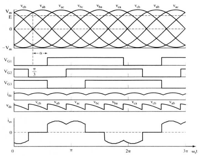
Output Voltage Waveforms
Average Output Voltage
Key Equation — Full-Converter
In terms of the RMS line voltage $V_L$:
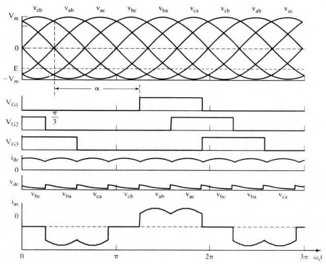
Voltage Polarity vs. Delay Angle
- $0° \leq \alpha < 90°$: $\;V_a > 0$ ⟹ Rectification (motoring mode)
- $\alpha = 90°$: $\;V_a = 0$
- $90° < \alpha \leq 180°$: $\;V_a < 0$ ⟹ Inversion (regeneration mode)
Two-Quadrant Operation
Quadrant I — Forward Motoring:
- $\alpha < 90° \Rightarrow V_a > 0$, $\;I_a > 0$
- $V_a > E_b$ (back-EMF)
- Power flow: Supply → Motor
Quadrant II — Forward Regenerative Braking:
- $\alpha > 90° \Rightarrow V_a < 0$, $\;I_a > 0$
- Motor still rotates forward ($E_b > 0$)
- $E_b > |V_a|$ drives current in the same direction
- Power flow: Motor → Supply
Important Note
Thyristors carry current in one direction only; it is the voltage $V_a$ that reverses, not $I_a$.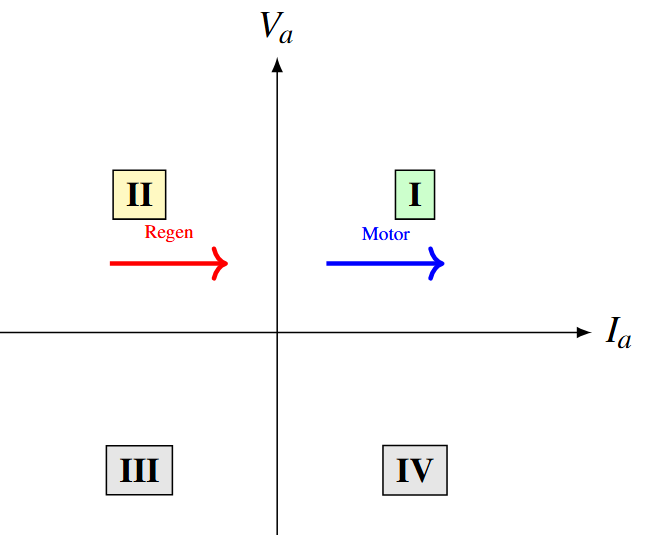
Regenerative Braking
Physical Mechanism:
- Motor is running forward; the load (or flywheel) has stored kinetic energy.
- Delay angle is increased beyond $90°$: converter output voltage $V_a$ becomes negative.
- Back-EMF $E_b$ (still positive) now exceeds $|V_a|$.
- Armature current $I_a$ continues to flow in the same (positive) direction.
- Instantaneous power $P = V_a \cdot I_a < 0$: energy flows from motor back to the AC supply.
- Motor decelerates — kinetic energy is returned to the grid.
Circuit Equation During Regeneration
$$E_b - v_a(t) = i_a(t)\,R_a + L_a\,\frac{di_a}{dt}$$where $v_a < 0$ and $E_b > 0$. The motor acts as a generator feeding power back through the converter (operating as an inverter) to the AC supply.
Requirement
The AC supply must be receptive (able to absorb power) for regeneration to succeed.Step-by-Step Transition from Motoring to Regeneration:
- Motor running in forward motoring mode: $\alpha < 90°$
- Controller gradually increases $\alpha$ toward $90°$
- At $\alpha = 90°$: $V_a = 0$; motor runs on stored energy
- $\alpha$ is further increased beyond $90°$: $V_a$ becomes negative
- Back-EMF $E_b$ (still positive) drives $I_a$ in the original direction
- Power reverses — motor begins to decelerate; energy returns to supply
Smooth Transition
Because $I_a$ never drops to zero during the changeover, the transition from motoring to regenerative braking is smooth and continuous — a major advantage of the full-converter topology.Input Power Factor
For perfectly smooth (continuous) armature current $I_a$, each supply line carries $+I_a$ for $120°$ and $-I_a$ for $120°$ per cycle, giving an RMS line current of:
The input displacement power factor is then:
Input Power Factor
| $\alpha$ | $\cos\alpha$ | Power Factor ($PF$) |
|---|---|---|
| $0°$ | $1.00$ | $0.955$ |
| $30°$ | $0.866$ | $0.827$ |
| $60°$ | $0.50$ | $0.478$ |
| $90°$ | $0.00$ | $0.000$ |
| $>90°$ | $< 0$ | Regenerative mode |
Field Circuit
The field circuit of a DC motor has a large time constant $\tau_f = L_f / R_f$. Using a full-converter for the field supply enables the following:
- A full-converter can apply negative voltage across the field winding, actively forcing the field current down faster.
- This reduces the time required for field reversal (important for four-quadrant drives) and for field weakening at high speed.
The field voltage supplied by a three-phase full-converter is:
Practical Choice
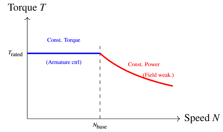
A single-phase full-converter is often sufficient for the field because the field power is typically only $1$–$5\%$ of the armature power.Speed Control Regions
Region 1 — Below Base Speed ($0$ to $N_{\text{base}}$):
- Field current held at rated value $I_{f,\text{rated}}$.
- Speed is varied by changing $\alpha_a$ — armature voltage control.
- Torque capability: constant (rated torque).
Region 2 — Above Base Speed ($N > N_{\text{base}}$):
- Armature voltage at maximum ($\alpha_a = 0°$).
- Speed is increased by reducing field current — field weakening.
- Torque capability: inversely proportional to speed (constant power operation).
Typical Applications
The full-converter drive is used in industrial applications that require two-quadrant control:
- Rolling mills
- Paper machines
- Textile machinery
- Cranes and hoists
- Elevators and lifts
- Machine tools (lathes, milling machines)
- Mining equipment
- Printing presses
- Extruders
- Winding and unwinding drives
Why Full-Converter?
These applications demand precise speed control, regenerative braking for energy recovery (especially cranes and hoists), and the ability to handle high power levels efficiently.Section 4
Three-Phase Dual-Converter Drives
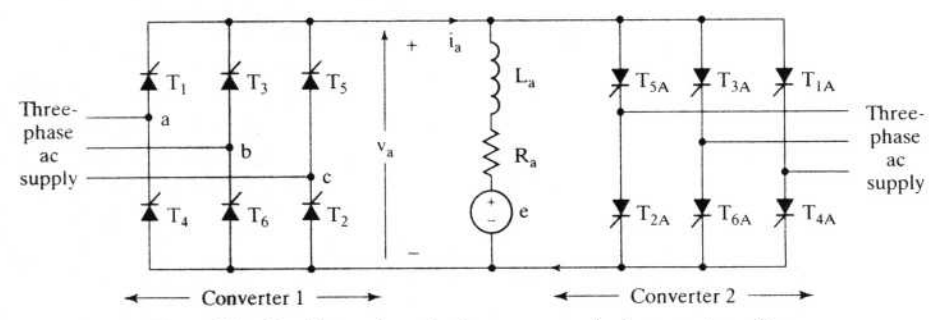
The three-phase dual-converter provides complete four-quadrant operation by connecting two three-phase full-converters in anti-parallel (back-to-back). This eliminates the need for mechanical contactors when reversing the motor direction, enabling fast, smooth, electronic reversal.
Converter Roles
- Converter P (positive): supplies positive armature voltage — operates in Quadrants I and II.
- Converter N (negative): supplies negative armature voltage — operates in Quadrants III and IV.
Cost and Complexity
The dual-converter is the most expensive and complex single-stage phase-controlled drive, requiring 12 thyristors in the armature circuit. It is justified only when frequent, fast reversals are required.Circuit Diagram
Operating Principle
- Converter P active ⟹ Quadrants I and II
- Forward motoring (Q-I): $\;\alpha_P < 90° \Rightarrow V_a > 0$
- Forward regeneration (Q-II): $\;\alpha_P > 90° \Rightarrow V_a < 0$
- Converter N active ⟹ Quadrants III and IV
- Reverse motoring (Q-III): $\;\alpha_N < 90° \Rightarrow V_a < 0$
- Reverse regeneration (Q-IV): $\;\alpha_N > 90° \Rightarrow V_a > 0$
Two Operating Modes
- Non-circulating current mode — preferred in practice; only one converter conducts at a time.
- Circulating current mode — both converters enabled simultaneously; requires an inter-group reactor.
Voltage Equations and Constraint
The average output voltage of each converter is:
For simultaneous operation without short-circuit, the following constraint must be maintained:
Anti-Parallel Constraint
This ensures $V_N = -V_P$, so the motor terminal voltage (which is $-V_N$ for Converter N) equals $V_P$. Both converters therefore agree on the motor terminal voltage in the average sense, while only one carries the load current at any time.
Result
Only one converter carries the load current at any time; the constraint prevents a short-circuit between the two converters.Four-Quadrant Summary
| Quadrant | Operation | Active Converter | Delay Angle | Sign of $V_a,\; I_a$ |
|---|---|---|---|---|
| I | Forward Motoring | P | $\alpha_P < 90°$ | $V_a > 0,\; I_a > 0$ |
| II | Forward Regeneration | P | $\alpha_P > 90°$ | $V_a < 0,\; I_a > 0$ |
| III | Reverse Motoring | N | $\alpha_N < 90°$ | $V_a < 0,\; I_a < 0$ |
| IV | Reverse Regeneration | N | $\alpha_N > 90°$ | $V_a > 0,\; I_a < 0$ |
Convention
$V_a$ is the voltage across the motor terminals (positive in the forward-motoring direction); $I_a$ is positive in the forward direction.Non-Circulating Current Mode
This is the preferred operating mode in modern drives:
- Only one converter conducts at a time; the other is fully blocked (all gate pulses removed).
- A dead time (typically $2$–$10\;\text{ms}$) is inserted between switching to allow the outgoing converter's current to fall to zero.
- No inter-group reactor is needed.
Switching Sequence (Converter P → Converter N):
- Ramp $\alpha_P$ to reduce $I_a$ smoothly toward zero.
- Wait for dead time; detect zero current.
- Block all gate pulses to Converter P.
- Enable gate pulses to Converter N with appropriate $\alpha_N$.
Advantages
No circulating-current losses; simpler reactor-free circuit; most commonly used mode in industry.Circulating Current Mode
In this mode, both converters are enabled simultaneously at all times with the constraint $\alpha_P + \alpha_N = 180°$ maintained. An inter-group reactor $L_r$ is connected between the two converter outputs to limit the circulating current.
Because $v_P + v_N \neq 0$ at every instant (only the averages cancel), a time-varying voltage appears across $L_r$, driving a circulating current:
Disadvantages
Continuous power loss in $L_r$; reactor is bulky and expensive; more complex control circuitry. Seldom used in modern drives.Field Circuit for Dual-Converter Drives
A single-phase or three-phase full-converter is recommended for the field supply:
- Provides two-quadrant field control (positive and negative $V_f$).
- Enables fast field reversal — essential for four-quadrant reversing drives.
- A single-phase full-converter is usually adequate (field power ≪ armature power).
Do Not Use a Semiconverter for the Field
A semiconverter cannot reverse $V_f$; field reversal would then rely on the slow natural decay of $I_f$ through $R_f$, making the overall drive sluggish.Advantages and Disadvantages
Advantages:
- Full four-quadrant operation
- Fast, smooth, electronic reversal — no contactors
- Regenerative braking in both directions
- High-performance dynamic response
Disadvantages:
- Highest device count: 12 thyristors (armature circuit)
- Most expensive and complex control
- Dead-time delay in non-circulating mode
- Higher harmonic injection into the supply
Typical Applications
Reversing rolling mills, mine hoists, machine-tool drives, and any process requiring frequent, rapid direction changes.Section 5
Comparison and Selection
Single-Phase vs. Three-Phase DC Drives
| Feature | Single-Phase | Three-Phase |
|---|---|---|
| Typical Power Range | Up to $100\;\text{kW}$ | $100\;\text{kW}$ – $1500\;\text{kW}$ |
| Ripple Frequency | $2f$ | $6f$ |
| Smoothing Inductor | Larger | Smaller |
| Motor Performance | Good | Excellent |
| Torque Pulsation | Higher | Lower |
| Efficiency | Good | Better |
| Cost per kW | Higher | Lower |
| Armature Current | More ripple; possibly discontinuous | Smoother; more continuous |
Comparison of Three-Phase Converter Types
| Feature | Semiconverter | Full-Converter | Dual-Converter |
|---|---|---|---|
| Quadrants | 1 | 2 | 4 |
| Thyristors (armature) | 3 | 6 | 12 |
| Diodes (armature) | 3 + FWD | 0 | 0 |
| Regeneration | No | Yes (1 direction) | Yes (both directions) |
| Reversal Method | Mechanical | With field reversal | Electronic |
| Power Range | Up to $115\;\text{kW}$ | Up to $1500\;\text{kW}$ | Up to $1500\;\text{kW}$ |
| $V_{a,\max}$ | $\dfrac{3\,V_{Lm}}{\pi}$ — identical for all three topologies | ||
| Cost | Low | Medium | High |
| Complexity | Low | Medium | High |
Drive Selection Guide
Choose Semiconverter if:
- Unidirectional load only
- No regeneration needed
- Cost must be minimised
- Power $\leq 115\;\text{kW}$
Choose Full-Converter if:
- Regenerative braking is needed
- Medium to high power requirement
- Best cost-performance trade-off is required
- Most common industrial choice
Choose Dual-Converter if:
- Frequent, fast reversals are required
- Four-quadrant operation is essential
- High dynamic performance is critical
- Cost can be justified by the application
General Rule
Start with the simplest topology that meets the application requirements — upgrade only if performance demands it.Section 6
Summary
Key Equations at a Glance
| Converter | Average Output Voltage | In terms of $V_L$ |
|---|---|---|
| Semiconverter | $\dfrac{3\sqrt{3}\,V_m}{2\pi}(1+\cos\alpha)$ | $\dfrac{3\sqrt{2}\,V_L}{2\pi}(1+\cos\alpha)$ |
| Full-Converter | $\dfrac{3\sqrt{3}\,V_m}{\pi}\cos\alpha$ | $1.35\,V_L\cos\alpha$ |
Notation and Input Power Factor
$V_m = \sqrt{2}\,V_p$ (peak phase voltage), $\quad V_{Lm} = \sqrt{2}\,V_L = \sqrt{3}\,V_m$ (peak line voltage), $\quad \alpha$ = firing-delay angle.
Full-converter input power factor (continuous armature current):
Summary Points
- Three-phase converters offer higher power capacity, lower ripple ($6f$), and better efficiency than single-phase counterparts, making them the industry standard for medium- to high-power DC drives.
- Semiconverter: One-quadrant operation ($V_a \geq 0$ always); uses a freewheeling diode; suitable for simple unidirectional loads with no regeneration requirement.
- Full-converter: Two-quadrant operation (motoring + regenerative braking); the workhorse of industrial DC drives; $V_a$ can be positive or negative by varying $\alpha$ from $0°$ to $180°$.
- Dual-converter: Four-quadrant operation by anti-parallel connection of two full-converters; enables fast electronic reversal; non-circulating current mode is preferred.
- Speed control: Below base speed uses armature voltage control (constant torque region); above base speed uses field weakening (constant power region).
- Field converter: Should be a full-converter (or better) for any drive that requires fast field reversal or field weakening above base speed.