Section 1 — Introduction to Single-Phase Drives
Basic Concept
Single-Phase Phase-Controlled DC Drive
A DC motor drive where the armature circuit is connected to the output of a single-phase controlled rectifier using thyristors (SCRs).
Key Operating Principles:
- Armature voltage controlled by varying the delay angle $\alpha_a$ of the converter
- Field current also controlled using a converter with delay angle $\alpha_f$
- Phase-controlled converters use line-commutated thyristors
- For improved power factor and reduced harmonics, forced-commutated converters (choppers) can be used
Basic Circuit Arrangement
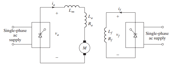
Important Components:
- Smoothing inductor $L_m$ reduces ripple current to acceptable magnitude
- Separate converters for armature and field circuits
- Essential at low delay angles and high speeds to prevent discontinuous current
- Free-wheeling diode (in semiconverter) improves performance
Motor Speed-Torque Relationship
DC Motor Fundamental Equations:
where $E_b = K_b \phi \omega_m$ is the back EMF.
Speed Equation:
Torque Equation:
Speed control is achieved by controlling $V_a$ (armature voltage) and $\phi$ (field flux).
Section 2 — Reversal Techniques
Field and Armature Reversal Methods
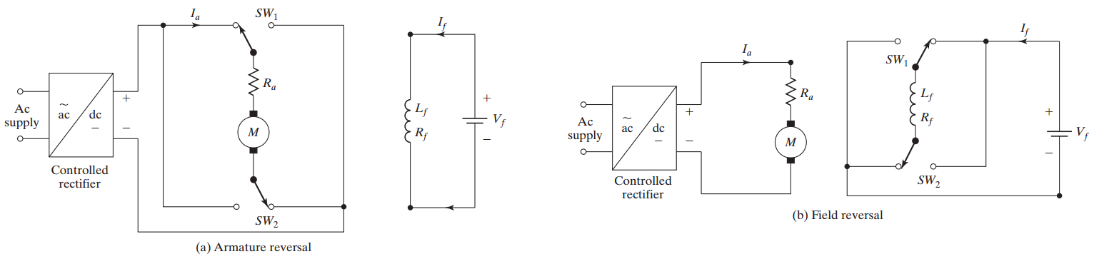
Reversal Techniques:
- Armature reversal: Using contactors SW1 and SW2 in armature circuit
- Field reversal: Using contactors SW1 and SW2 in field circuit
Safety Considerations
- Reversal performed at zero armature current to avoid voltage surges
- Dead time of 2–10 ms provided to ensure zero current
- Field reversal takes longer due to large time constant ($L_f / R_f$)
- Only one direction should be reversed at a time
Section 3 — Types of Single-Phase Drives
Classification of Single-Phase Drives
Single-phase drives can be subdivided into four types:
-
Single-Phase Half-Wave Converter Drives
- Armature current normally discontinuous
- High ripple content
- Not commonly used in practice
-
Single-Phase Semiconverter Drives
- One-quadrant operation
- Applications up to 15 kW
- Lower cost, simpler control
-
Single-Phase Full-Converter Drives
- Two-quadrant operation
- Most commonly used
- Regenerative braking capability
-
Single-Phase Dual-Converter Drives
- Four-quadrant operation
- Maximum flexibility
- Higher cost and complexity
Section 4 — Single-Phase Semiconverter Drives
Semiconverter Drive Configuration
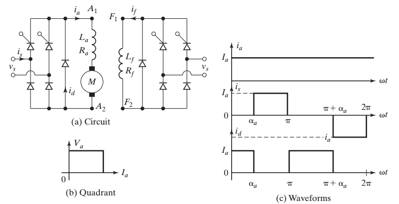
Characteristics:
- One-quadrant drive (forward motoring only)
- Limited to applications up to 15 kW
- Two thyristors and two diodes
- Free-wheeling diode improves performance and reduces ripple
- Current waveforms for highly inductive load
Semiconverter — Voltage Equations
Average Armature Voltage:
where $V_m$ is the peak value of the AC supply voltage.
Average Field Voltage (if semiconverter used):
Control Range
- Delay angle $\alpha_a$ varies from 0 to $\pi$ radians
- Voltage can be controlled from $\frac{2V_m}{\pi}$ (at $\alpha_a = 0$) to 0 (at $\alpha_a = \pi$)
- Output voltage is always positive (unidirectional)
Semiconverter — Current Analysis
RMS Armature Current:
For continuous conduction mode:
Current Ripple:
- Peak-to-peak ripple depends on $L_m$, load, and $\alpha_a$
- Critical inductance to maintain continuous conduction
- Free-wheeling diode reduces negative voltage period
⚠ Important Note
For discontinuous conduction, analysis becomes more complex and average voltage decreases.
Section 5 — Single-Phase Full-Converter Drives
Full-Converter Drive Configuration
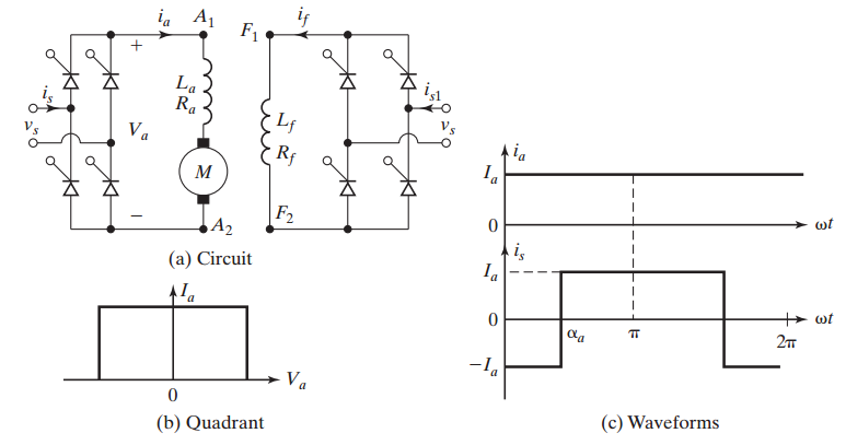
Characteristics:
- Two-quadrant drive (forward motoring and forward braking)
- Applications up to 15 kW
- Four thyristors in bridge configuration
- Armature converter provides $+V_a$ or $-V_a$
- Operates in first and fourth quadrants
Full-Converter — Voltage Equations
Average Armature Voltage:
Average Field Voltage (if full-converter used):
Advantages over Semiconverter
- Can reverse armature voltage polarity
- Enables regenerative braking (energy recovery)
- Full converter in field circuit can reduce field current faster
- Better control range: $-\frac{2V_m}{\pi}$ to $+\frac{2V_m}{\pi}$
- Higher efficiency during regeneration
Full-Converter — Quadrant Operation
Operating Modes:
-
First Quadrant (Motoring): $0 \leq \alpha_a < 90°$
- Positive armature voltage and current
- Motor runs in forward direction
- Power flows from supply to motor
-
Fourth Quadrant (Regenerative Braking): $90° < \alpha_a \leq 180°$
- Negative armature voltage, positive current direction
- Energy flows back to supply
- Motor acts as generator
- Speed decreases while maintaining same direction
⚠ Extending to Four Quadrants
Reversal of armature terminals or field polarity allows operation in second and third quadrants for complete four-quadrant capability.
Full-Converter — Performance Parameters
RMS Supply Current:
Input Power Factor:
Harmonic Content:
- Dominant harmonics: 2nd, 4th, 6th in output voltage
- Supply current harmonics: odd harmonics (3rd, 5th, 7th, etc.)
- Total Harmonic Distortion (THD) increases with $\alpha_a$
Section 6 — Single-Phase Dual-Converter Drives
Dual-Converter Drive Configuration
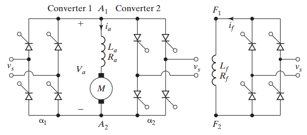
Configuration:
- Two single-phase full-wave converters connected in anti-parallel
- Converter 1: Positive armature voltage $+V_a$
- Converter 2: Negative armature voltage $-V_a$
- Only one converter operates at a time
- Circulating current-free operation
Dual-Converter — Voltage Equations
Converter 1 (Delay angle $\alpha_{a1}$):
Converter 2 (Delay angle $\alpha_{a2}$):
Control Strategy:
This ensures both converters produce equal and opposite voltages when idle.
Field Voltage (Full converter):
Dual-Converter — Four-Quadrant Operation
Converter 1 Operation:
- First quadrant: Forward motoring ($\alpha_{a1} < 90°$)
- Fourth quadrant: Forward regenerative braking ($\alpha_{a1} > 90°$)
Converter 2 Operation:
- Second quadrant: Reverse regenerative braking ($\alpha_{a2} > 90°$)
- Third quadrant: Reverse motoring ($\alpha_{a2} < 90°$)
Applications
- Four-quadrant drive capability without mechanical contactors
- Applications up to 15 kW
- Suitable for applications requiring frequent reversals
- Examples: Rolling mills, hoists, elevators
Dual-Converter — Mode Transition
Switching Between Converters:
- Detect zero current crossing in active converter
- Provide dead time (2–10 ms)
- Block gate pulses to previous converter
- Enable gate pulses to new converter
⚠ Circulating Current Issue
If both converters are fired simultaneously:
- Large circulating current flows: $i_{\text{circ}} = \frac{V_{a1} - V_{a2}}{R_{\text{eq}}}$
- Can damage thyristors
- Requires current-limiting reactor in circulating-current mode
- Non-circulating mode preferred for lower losses
Section 7 — Comparison of Drive Types
Comparison of Single-Phase Drive Types
| Feature | Semiconverter | Full-Converter | Dual-Converter |
|---|---|---|---|
| Quadrants | 1 | 2 | 4 |
| Power Range | Up to 15 kW | Up to 15 kW | Up to 15 kW |
| Thyristors | 2 | 4 | 8 |
| Voltage Control | $\frac{V_m}{\pi}(1+\cos\alpha_a)$ | $\frac{2V_m}{\pi}\cos\alpha_a$ | $\frac{2V_m}{\pi}\cos\alpha_a$ |
| Regeneration | No | Yes | Yes |
| Reversal Method | Mechanical | Field/armature | Converter switching |
| Complexity | Low | Medium | High |
| Cost | Lowest | Medium | Highest |
| Power Factor | Better | Poor at high $\alpha$ | Poor at high $\alpha$ |
Selection Criteria:
- Simple unidirectional applications: Semiconverter
- Need for regeneration: Full-converter
- Frequent reversals without contactors: Dual-converter
Section 8 — Key Design Considerations
Important Design Considerations
1. Smoothing Inductor Selection:
- Connected in series with armature circuit
- Minimum inductance: $L_{m,\min} = \frac{V_m R_a}{2\pi f \Delta I_a}$ (approximate)
- Reduces ripple current to acceptable magnitude (typically < 10% of rated)
- Essential at low delay angles to prevent discontinuous current
2. Field Circuit Design:
- Semi- or full-converter for field control
- Full converter preferred for faster field current reduction
- Large time constant ($\tau_f = L_f/R_f$) affects reversal time
- Field forcing for rapid flux changes
3. Protection and Safety:
- Zero current detection before reversal
- Dead time provision (2–10 ms)
- Overvoltage protection (snubber circuits)
- Overcurrent protection (fuses, circuit breakers)
Converter Selection for Field Circuit
Semiconverter Option:
- Lower cost
- Simpler control
- Unidirectional power flow
- Slower field weakening
- Natural commutation only
Full Converter Option:
- Higher cost
- More complex control
- Bidirectional capability
- Faster field weakening
- Can reverse field voltage
Recommendation
Full converter is preferable for the field circuit due to its ability to reverse voltage polarity and reduce field current much faster than a semiconverter, enabling rapid field weakening for field-weakened operation.
Continuous vs. Discontinuous Conduction
Continuous Conduction Mode (CCM):
- Armature current never reaches zero
- Occurs when $L_m$ is large or load is heavy
- Voltage equations derived earlier are valid
- Better performance, lower ripple
Discontinuous Conduction Mode (DCM):
- Armature current becomes zero for part of cycle
- Occurs when $L_m$ is small or load is light
- Average voltage is higher than CCM for same $\alpha_a$
- Analysis is more complex
- Higher current and voltage ripple
⚠ Design Guideline
Design $L_m$ to ensure continuous conduction at minimum expected load.
Section 9 — Power Quality and Harmonics
Harmonics in Single-Phase Drives
Output Voltage Harmonics:
- Fundamental frequency: $2f$ (for full-wave converters)
- Dominant harmonics: $2f$, $4f$, $6f$, etc.
- Amplitude decreases with harmonic order
- Smoothing inductor filters high-frequency harmonics
Supply Current Harmonics:
- Odd harmonics predominate: 3rd, 5th, 7th, 11th, 13th, etc.
- $n$-th harmonic current: $I_n \approx \frac{I_1}{n}$
- Total Harmonic Distortion: $\text{THD} = \frac{\sqrt{\sum_{n=2}^{\infty} I_n^2}}{I_1}$
- Typical THD: 40–80% depending on operating point
Mitigation Techniques
- AC line filters
- Multi-pulse converters (for higher power ratings)
- Active power filters
Power Factor in Phase-Controlled Drives
Displacement Power Factor:
Distortion Factor:
Total Power Factor:
⚠ Power Factor Issues
- Power factor decreases with increasing $\alpha_a$
- At $\alpha_a = 90°$, DPF = 0, no real power transfer
- Poor power factor leads to reactive power penalties
- Capacitor banks may be required for PF correction
Section 10 — Summary
Key Takeaways
- Single-phase phase-controlled drives use thyristor-based controlled rectifiers to vary DC motor armature voltage
- Four main types: half-wave (rarely used), semiconverter (1-quadrant), full-converter (2-quadrant), and dual-converter (4-quadrant)
- Smoothing inductor $L_m$ is essential to reduce current ripple and maintain continuous conduction
- Field or armature reversal required for opposite direction operation
- Safety measures include zero current detection and dead time before reversal
- Full-converter preferred for field circuit due to faster current reduction capability
- Selection depends on quadrant requirements, power level, and application needs
- Power quality concerns: harmonics and poor power factor at high delay angles
Voltage Equation Summary
| Drive Type | Armature Voltage | Field Voltage |
|---|---|---|
| Semiconverter | $V_a = \dfrac{V_m}{\pi}(1+\cos\alpha_a)$ | $V_f = \dfrac{V_m}{\pi}(1+\cos\alpha_f)$ |
| Full-converter | $V_a = \dfrac{2V_m}{\pi}\cos\alpha_a$ | $V_f = \dfrac{2V_m}{\pi}\cos\alpha_f$ |
| Dual-converter | $V_a = \pm\dfrac{2V_m}{\pi}\cos\alpha_{a1,2}$ | $V_f = \dfrac{2V_m}{\pi}\cos\alpha_f$ |
All delay angles: $0 \leq \alpha \leq \pi$ radians
Continuous conduction mode assumed
Practical Applications
Typical Applications by Type:
-
Semiconverter Drives:
- Fans, blowers, pumps
- Conveyors (unidirectional)
- Simple machine tools
-
Full-Converter Drives:
- Machine tools with regenerative braking
- Printing presses
- Paper and textile mills
-
Dual-Converter Drives:
- Reversing rolling mills
- Mine hoists and elevators
- Cranes with frequent direction changes