By the end of this lecture, you will be able to:
Identify the main power semiconductor devices used in electric drives
Explain the characteristics and operating principles of power diodes
Understand thyristor (SCR) operation, triggering, and commutation
Compare power transistors: BJT, MOSFET, and IGBT
Apply device selection criteria for motor drive applications
Introduction to Power Devices
What We've Covered:
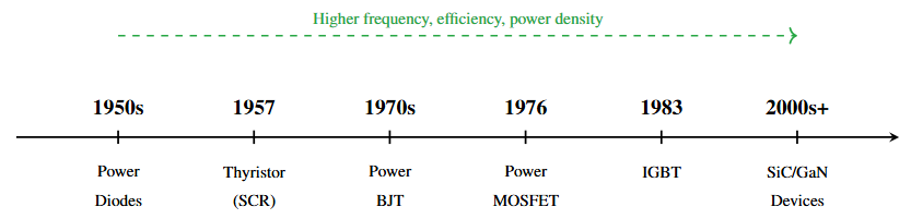
Evolution of electric drives
Three drive configurations
Five functional blocks
Motor types and selection
Power sources (AC/DC)
Today's Focus:
Power semiconductor devices
The heart of power converters
Enable control and efficiency
Device characteristics
Selection for drives
Key Point
Power electronic converters are the enabling technology for modern drives—and power semiconductor devices are the building blocks of these converters!
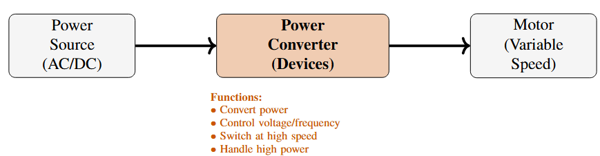
Why Power Devices Matter
Determine converter efficiency, cost, and performance
Enable fast switching for PWM control
Must handle high voltage and current simultaneously
Critical for drive reliability and protection
Three main categories based on control:
Uncontrolled Devices (Diodes)
Turn ON and OFF automatically
Used in uncontrolled rectifiers
Semi-Controlled Devices (Thyristors/SCRs)
Controlled turn ON, natural turn OFF
Used in phase-controlled rectifiers
Fully-Controlled Devices (Transistors)
Controlled turn ON and turn OFF
BJT, MOSFET, IGBT
Used in choppers, inverters, modern drives
Current Status
Dominant: IGBT for drives (1–10 kW range), thyristors for high power
Growing: SiC MOSFETs for high efficiency, high temperature
Declining: Power BJTs, being replaced by IGBTs
Power Diodes
Symbol and Structure:
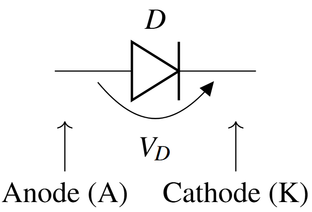
Characteristics:
Two-terminal device
Uncontrolled (no gate)
Conducts when forward biased (VA > VK)
Blocks when reverse biased
Acts as automatic switch
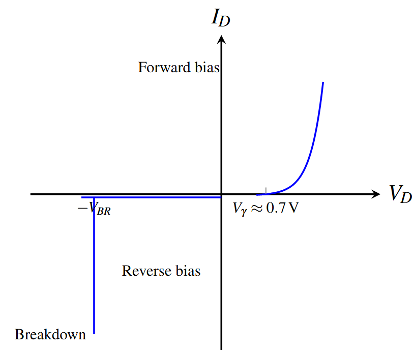
I–V Characteristic:
Key Parameters:
Forward voltage drop: VF ≈ 0.7–1.5 V
Reverse blocking voltage
Forward current rating
Three Operating Regions
Forward Conduction (VD > VF):
Diode conducts with small forward drop
Current limited by external circuit
Power loss: P = VF × IF
Reverse Blocking (VD < 0):
Very small leakage current (μA)
Blocks voltage up to rated value
Negligible power loss
Reverse Breakdown (VD < -VBR):
Avalanche breakdown occurs
Large reverse current flows
Device may be damaged
Must be avoided in normal operation
| Parameter | Symbol | Typical Values | Significance |
|---|---|---|---|
| Average forward current | IF(AV) | 10 A – 5000 A | Continuous rating |
| RMS current | IF(RMS) | 1.11 × IF(AV) | Heating calculation |
| Peak repetitive current | IFSM | 10–20 × IF(AV) | Surge capability |
| Forward voltage drop | VF | 0.7 V – 1.5 V | Conduction loss |
| Reverse voltage | VRRM | 50 V – 10 kV | Blocking capability |
| Reverse recovery time | trr | 10 ns – 10 μs | Switching speed |
| Junction temperature | Tj | -40°C to 150°C | Operating range |
Critical Parameters for Drive Applications
Current rating: Must handle motor current + margin
Voltage rating: 2–3× supply voltage for safety
Recovery time: Fast recovery for high-frequency applications
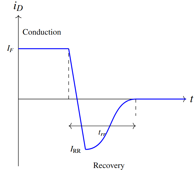
Critical dynamic characteristic:
What Happens:
Diode conducting forward current
Voltage reverses suddenly
Stored charge must be removed
Diode conducts reverse briefly
Reverse current peaks (IRR)
Then diode blocks
Consequences:
Switching losses
EMI generation
Limits switching frequency
Voltage spikes in circuit
Recovery Time Components:
Types:
Standard recovery: trr = 1–10 μs
Fast recovery: trr = 100–500 ns
Ultra-fast: trr < 100 ns
General Purpose Diodes
Standard recovery time (1–10 μs)
Line frequency applications (50/60 Hz)
Uncontrolled rectifiers
Fast Recovery Diodes (FRD)
Recovery time: 100–500 ns
Switching frequencies: 1–20 kHz
Freewheeling diodes in converters
Schottky Diodes
Very fast switching (< 10 ns)
Lower forward drop (0.3–0.5 V)
Low voltage applications (< 200 V)
High-frequency switching
1. Uncontrolled Rectifiers:
Convert AC to fixed DC
Single-phase and three-phase
Simple DC motor drives
Input stage of VFDs
2. Freewheeling Diodes:
Provide path for inductive current
Protect switching devices
Energy recovery
Essential in choppers and inverters
3. Voltage Clamping:
Snubber circuits
Overvoltage protection
Transient suppression
4. Brake Choppers:
Regenerative braking
Dynamic braking resistors
DC bus voltage control
Key Point
Even in fully-controlled drives (with IGBTs), diodes are essential components for freewheeling and protection!
Thyristors (SCR)
Symbol and Structure:
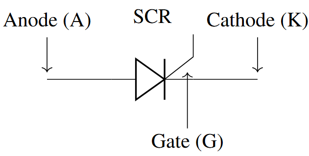
Characteristics:
Three-terminal device
Semi-controlled (ON control only)
Four-layer PNPN structure
Latching behavior
High power capability
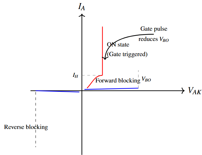
Operating Principle:
Forward biased but OFF (blocking)
Gate pulse applied (IG > IGT)
Device turns ON (latches)
Gate loses control
Remains ON while IA > IH
Turns OFF when current falls below holding current
Key Terms:
IGT: Gate trigger current
IH: Holding current
IL: Latching current
Operating States
Forward blocking: VAK positive, no gate pulse, device OFF
Forward conduction: Gate triggered, device ON, low voltage drop
Reverse blocking: VAK negative, device OFF (like diode)
Gate Triggering (Most Common)
Short positive pulse to gate
VG ≈ 1–2 V, IG > 10–200 mA (device dependent)
Pulse width: 10–100 μs
Used in all controlled applications
Forward Voltage Triggering
VAK exceeds breakover voltage VBO
Uncontrolled, to be avoided
dv/dt Triggering
Rapid voltage rise can trigger
Undesired, prevented by snubbers
Temperature Triggering
High temperature can cause turn-on
Prevented by proper cooling
Practical Design
Gate trigger circuits must provide sufficient pulse amplitude, width, and rise time for reliable triggering under all operating conditions.
Problem: Gate cannot turn OFF thyristor once triggered!
Turn-OFF Condition
Thyristor turns OFF when anode current falls below holding current (IH) for sufficient time (turn-off time tq).
Commutation Types:
Natural (Line) Commutation
AC supply voltage reverses naturally
Current becomes zero automatically
Used in phase-controlled rectifiers
Simple, no extra circuitry needed
Forced Commutation
External circuit forces current to zero
Required for DC applications (choppers)
Uses capacitors, inductors, auxiliary devices
Complex and adds cost
Important Ratings:
VDRM: Forward blocking voltage
VRRM: Reverse blocking voltage
IT(AV): Average ON-state current
ITSM: Surge current rating
di/dt rating: Max current rise
dv/dt rating: Max voltage rise
tq: Turn-off time
Protection Requirements:
Overvoltage:
Voltage rating 2–3× normal
Crowbar circuits
Snubber circuits
Overcurrent:
Fast-acting fuses
Current limiting reactors
dv/dt protection:
RC snubber across device
Prevents false triggering
di/dt protection:
Series inductors
Limits current rise rate
Primary Applications:
Phase-Controlled Rectifiers
DC motor drives (declining)
Controlled DC voltage output
1-phase and 3-phase
Line frequency (50/60 Hz)
AC Voltage Controllers
Soft starters for induction motors
Reduced voltage starting
Simple speed control (limited)
Cycloconverters
Direct AC-AC conversion
Large low-speed drives
Ship propulsion, cement mills
Advantages:
Very high power capability (MW range)
High voltage ratings (to 10 kV)
Robust and reliable
Low ON-state losses and simple gate drive
Disadvantages:
No turn-OFF control
Poor power factor and high harmonic content
Limited to line frequency
Being replaced by IGBTs
Current Trend
Thyristors declining in new installations, replaced by IGBT-based converters. Still dominant in very high power (>5 MW) and legacy systems.
Power Transistors
Fully-controlled devices – both turn-ON and turn-OFF controlled
| Parameter | BJT | MOSFET | IGBT |
|---|---|---|---|
| Control type | Current | Voltage | Voltage |
| Input impedance | Low | Very High | Very High |
| Switching speed | Medium | Very Fast | Fast |
| ON-state loss | Low | Medium | Low |
| Switching loss | High | Low | Medium |
| Voltage rating | Medium (1.2 kV) | Medium (1 kV) | High (6.5 kV) |
| Current rating | High (500 A) | Medium (200 A) | Very High (3600 A) |
| Safe Operating Area | Small | Large | Large |
| Drive complexity | Complex | Simple | Simple |
| Cost | Low | Medium | Medium |
| Current status | Declining | Low-medium power | Dominant |
Symbol:
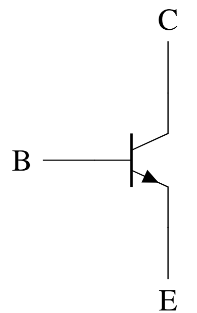
Characteristics:
Current-controlled device
IC = β × IB
Low ON-state voltage (0.5–2 V)
Requires continuous base current
Second breakdown issue
Advantages:
Low saturation voltage
High current capability
Good for linear applications
Disadvantages:
Current-driven (complex drive)
Slow switching speed and high switching losses
Second breakdown risk
Negative temperature coefficient
Being phased out
Status
Power BJTs largely replaced by MOSFETs and IGBTs in modern drives. Rarely used in new designs.
Symbol (N-channel):
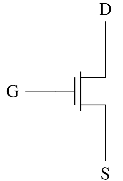
Characteristics:
Voltage-controlled device
Very high input impedance
ID controlled by VGS
Fast switching (<100 ns)
Positive temp coefficient
Advantages:
Very fast switching and simple gate drive
No second breakdown
Positive temp coefficient (parallel operation safe)
Low switching losses
Disadvantages:
Higher ON-state resistance
Limited voltage (<1 kV) and current rating
More expensive at high power
Applications
Ideal for: Low-medium power (<10 kW), high frequency (>20 kHz), DC-DC converters, switched-mode power supplies, low voltage motor drives.
Symbol:
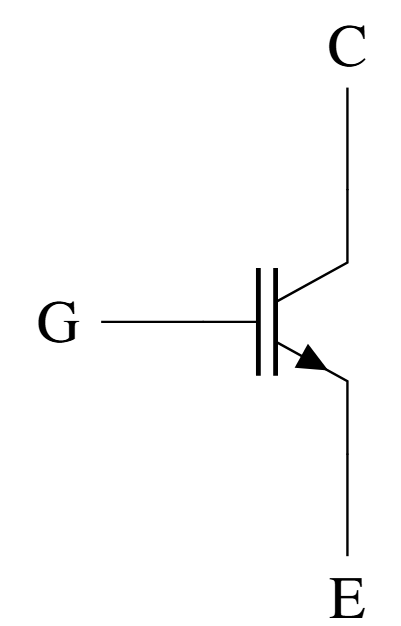
Hybrid Device:
Combines MOSFET input + BJT output
MOSFET: High impedance gate
BJT: Low ON-state drop
Best of both worlds!
Advantages:
Voltage-controlled (simple drive)
Low ON-state voltage (like BJT)
High voltage/current ratings
Medium switching speed (good balance)
Large Safe Operating Area and easy to parallel
Disadvantages:
Slower than MOSFET
Tail current during turn-off
More expensive than thyristors
Industry Standard
IGBT is the workhorse of modern motor drives! Dominant in 1 kW to 1 MW range, PWM inverters, VFDs, traction drives, renewable energy converters.
Voltage Ratings:
Standard: 600 V, 1200 V, 1700 V
High voltage: 3.3 kV, 4.5 kV, 6.5 kV
Suitable for industrial drives
Current Ratings:
Low power: 10–50 A
Medium power: 50–300 A
High power: 300–3600 A
Modular design for higher
Switching Frequency:
Typical: 2–20 kHz
Low voltage: up to 50 kHz
Higher than thyristors
Lower than MOSFETs
Performance Features:
VCE(sat) = 1.5–3 V (low loss)
Turn-on time: 0.5–2 μs and Turn-off time: 1–5 μs
Tail current increases losses
Junction temp: up to 175°C
Module Configurations:
Single switch
Half/Full-bridge (2/4 IGBTs + diodes)
Six-pack (3-phase inverter), Seven-pack (inverter + brake)
Gate Drive Requirements
Gate voltage: +15 V (ON), -15 V or 0 V (OFF). Gate resistor limits current. Isolated power supply needed. Commercial gate driver ICs available.
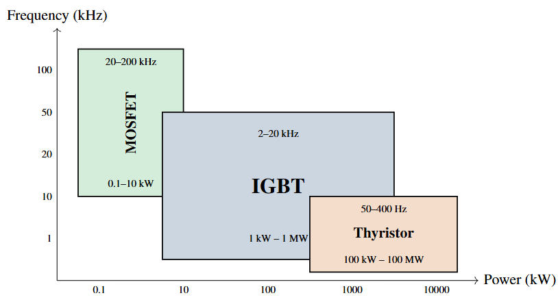
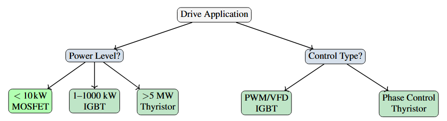
Selection Guideline
<10 kW, high frequency: MOSFET
1–1000 kW, PWM control: IGBT
>5 MW, line frequency: Thyristor
Device Selection Criteria
Key factors to consider:
Power Level
Motor power rating determines device current
Voltage rating based on supply + safety margin
Switching Frequency
PWM inverters: 2–20 kHz → IGBT
High frequency DC-DC: >20 kHz → MOSFET
Phase control: Line frequency → Thyristor
Control Requirements
Four-quadrant, regeneration → Fully-controlled (IGBT)
Simple rectification → Thyristor or diode
Efficiency
Consider ON-state + switching losses
IGBT best balance for most drives
Cost
Device cost + drive circuit + cooling
Total system cost matters
| Application | Power | Converter | Device | Justification |
|---|---|---|---|---|
| DC motor drive (legacy) | 50 kW | Phase-controlled rectifier | Thyristor | Line freq, high power, Simple, robust |
| VFD for pump | 15 kW 400 V | 3-phase inverter, Diode rectifier + | IGBT modules | PWM control, efficiency, Standard solution |
| Servo drive | 2 kW | PWM inverter, High frequency | IGBT or MOSFET | Fast response, High frequency OK |
| EV inverter | 100 kW 400 V DC | 3-phase inverter | IGBT 1200 V | High power, efficiency, Automotive qualified |
| DC-DC converter | 5 kW 48 V | Buck/Boost 50–100 kHz | MOSFET | High frequency, Low voltage, fast |
| Large mill drive | 5 MW | Cycloconverter | Thyristor 6.5 kV | Very high power, Line frequency |
Critical for device reliability and performance:
Power Loss Components:
Conduction losses
Pcond = VCE(sat) × Iavg
Switching losses
Psw = ½VDC × I × (ton+toff) × fsw
Gate drive losses (small)
Total Power Loss:
Ptotal = Pcond + Psw
Cooling Methods:
Natural convection
<10 W; Simple heatsinks
Forced air cooling
10 W – 5 kW; Fans + heatsinks
Most common in drives
Liquid cooling
>5 kW; Water/glycol for high power density
Thermal Design:
Junction temperature <125-150°C
Thermal resistance calculation
Heatsink sizing
Temperature monitoring
Overcurrent Protection:
Fast-acting fuses
Electronic current limiting
Desaturation detection (IGBT)
Response time <10 μs
Overvoltage Protection:
Snubber circuits (RC, RCD)
Voltage clamping diodes
Active voltage control
Proper PCB layout
Overtemperature Protection:
Thermistor/thermocouple
Thermal shutdown
Derating at high temp
Cooling system monitoring
Gate Drive Protection:
Isolated power supplies
Undervoltage lockout (UVLO)
Shoot-through prevention
Dead-time insertion
Critical
Protection must be fast enough to save the device. Typical IGBT failure time under fault: 5–10 μs!
Emerging Technologies
Next generation: Silicon Carbide (SiC) and Gallium Nitride (GaN)
SiC MOSFETs:
Voltage: 650 V – 3.3 kV
Very fast switching (<50 ns)
High temperature (200°C)
Lower losses than Si IGBT
Higher frequency possible
Smaller passive components
Cost: 3–5× Si devices
Applications:
EV inverters (Tesla, others)
High-efficiency drives
Aerospace
Renewable energy
Advantages over Silicon:
10× breakdown field strength
3× thermal conductivity
Higher switching frequency
Lower switching losses
Smaller heatsinks
Higher power density
Better efficiency (98–99%)
Challenges:
High cost (decreasing)
Limited suppliers
Gate drive design critical
EMI considerations
Future Outlook
SiC adoption growing rapidly. Expected to dominate EV and high-performance drives by 2030. Cost parity with Si IGBTs anticipated by 2028–2030.
Summary
Power devices are the heart of converters, enabling control and efficiency
Three categories: Uncontrolled (diodes), Semi-controlled (thyristors), Fully-controlled (transistors)
Diodes: Automatic switching, essential for rectification and freewheeling
Thyristors: Semi-controlled, high power capability, declining in new designs
IGBT: Industry standard for modern drives (1 kW – 1 MW), best balance of performance
MOSFET: Fast switching, low-medium power, high frequency applications
Selection criteria: Power level, frequency, control requirements, efficiency, cost
Future: Wide bandgap devices (SiC, GaN) for higher efficiency and power density