Introduction to DC Machine Modeling
By the end of this lecture, you will be able to:
Understand the need for mathematical modeling of DC machines
Recall the construction and operating principle of DC machines
Derive the fundamental torque and EMF equations
Identify machine parameters and their physical significance
Express equations in compact forms suitable for analysis
Importance of Mathematical Modeling:
Predict machine behavior under different operating conditions
Design control systems for speed and torque regulation
Analyze steady-state and dynamic performance
Optimize drive system efficiency
Simulate before physical implementation
Model Applications
Motor starting and braking studies
Speed control design
Energy consumption analysis
Fault diagnosis and condition monitoring
Traditional Applications:
Rolling mills
Paper mills
Traction systems
Machine tools
Hoists and cranes
Modern Applications:
Electric vehicles
Robotics and automation
CNC machines
Aerospace actuators
Precision servo systems
Key Advantages
Simple and precise speed control
High starting torque capability
Wide speed range operation
Independent control of flux and torque
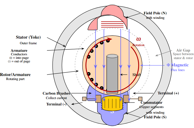
Review of DC Machine Construction
1. Stator (Field System)
Provides mechanical support and magnetic return path
Houses field poles with field windings
Produces the main magnetic field
Can use electromagnets or permanent magnets
2. Rotor (Armature)
Cylindrical laminated core mounted on shaft
Contains armature windings in slots
Carries armature current during operation
Rotates within the magnetic field
3. Commutator and Brush Assembly
Mechanical rectifier for DC operation
Maintains unidirectional torque
Ensures current reversal at appropriate instants
Fundamental Principle
When a current-carrying conductor is placed in a magnetic field, it experiences a mechanical force (Lorentz force).
Fleming's Left-Hand Rule (Motor Action):
First finger: Direction of magnetic field (N to S)
Second finger: Direction of current
Thumb: Direction of force/motion
Key Concept
Maximum torque occurs when the magnetic field and armature current interact with conductors positioned perpendicular to the field
The Problem Without Commutator
As the rotor rotates, conductors move from one pole to another. Without commutation, the force direction would reverse, causing oscillation instead of continuous rotation.
The Solution: Commutator Action
The commutator reverses the current direction in the armature conductors at the right instant (when crossing the magnetic neutral axis), ensuring:
Unidirectional electromagnetic torque
Continuous rotation in one direction
Automatic switching synchronized with rotor position
Commutator Construction:
Copper segments insulated from each other
Mounted on rotor shaft
Carbon/graphite brushes make sliding contact
EMF Equation Derivation
Faraday's Law of Electromagnetic Induction:
For a conductor moving in a magnetic field:
where:
\(B\) = magnetic flux density (T)
\(l\) = active length of conductor (m)
\(v\) = velocity of conductor (m/s)
In DC Machine
Multiple conductors on the rotor cut the magnetic flux as the machine rotates, inducing EMF in each conductor. Total EMF depends on machine construction and rotational speed.
Machine Parameters:
\(P\) = Number of poles
\(\phi\) = Flux per pole (Wb)
\(Z\) = Total armature conductors
\(n\) = Speed in rpm
\(a\) = Number of parallel paths
\(\omega_m\) = Angular speed (rad/s)
\(E\) = Induced EMF (V)
Step 1: Flux Cut by One Conductor per Revolution
Each conductor cuts flux from \(P\) poles in one revolution:
Step 2: Time for One Revolution
If speed is \(n\) rpm:
Step 3: EMF Induced in One Conductor
Using Faraday's law:
Step 4: Total EMF with All Conductors
With \(Z\) conductors in \(a\) parallel paths:
Conductors in series per path = \(Z/a\)
EMFs of conductors in series add up
Expressing in terms of angular velocity:
Angular velocity in rad/s: \(\omega_m = \frac{2\pi n}{60}\)
Therefore: \(n = \frac{60\omega_m}{2\pi}\)
Substituting in EMF equation:
Standard Compact Form
where the machine constant is:
For constant flux operation:
If flux \(\phi\) is maintained constant:
where \(K_e = K_a\phi\) is the EMF constant (V·s/rad)
Lap Winding:
Number of parallel paths: \(a = P\)
Higher current rating
Lower voltage rating
Used in high-current applications
Wave Winding:
Number of parallel paths: \(a = 2\)
Lower current rating
Higher voltage rating
Used in high-voltage applications
Torque Equation Derivation
Force on a Current-Carrying Conductor:
When a conductor carrying current \(i\) is placed in a magnetic field of flux density \(B\):
where \(l\) is the active length of the conductor.
Torque from One Conductor:
If the conductor is at radius \(r\) from the shaft center:
Assumptions:
Uniform flux distribution under pole faces
All conductors carry equal current
Negligible flux fringing
Total Force on All Conductors:
Average flux density: \(B_{\text{av}} = \frac{P\phi}{\pi Dl}\)
where \(D\) is armature diameter and \(l\) is axial length.
Current per conductor: \(i_c = \frac{I_a}{a}\)
where \(I_a\) is total armature current and \(a\) is parallel paths.
Total force on \(Z\) conductors:
Electromagnetic Torque:
Standard Torque Equation
where \(K_a = \frac{PZ}{2\pi a}\) (same constant as in EMF equation)
For constant flux operation:
where \(K_t = K_a\phi\) is the torque constant (N·m/A)
Recall:
Power balance (neglecting losses):
Substituting:
Important Result
In SI units with consistent definitions (V·s/rad and N·m/A), the EMF constant equals the torque constant numerically!
Field flux in terms of field current:
For a linear magnetic circuit (unsaturated region):
where:
\(N_f\) = number of field turns per pole
\(I_f\) = field current
\(\mathcal{R}_m\) = magnetic reluctance
Substituting in torque equation:
Two-Current Torque Expression
where \(K_f = \frac{K_a N_f}{\mathcal{R}_m}\) is a proportionality constant
Summary and Key Equations
EMF Equations
Torque Equations
Machine Constants
| Parameter | Symbol | Significance |
|---|---|---|
| Number of poles | \(P\) | Flux distribution |
| Total conductors | \(Z\) | Current-carrying capacity |
| Parallel paths | \(a\) | Voltage/current rating |
| Flux per pole | \(\phi\) | Field strength |
| Machine constant | \(K_a\) | Construction dependent |
| EMF constant | \(K_e\) | Speed-voltage relation |
| Torque constant | \(K_t\) | Current-torque relation |
Key Insight
For a given DC machine, \(P\), \(Z\), and \(a\) are fixed by construction. Therefore, \(K_a\) is constant. If field flux \(\phi\) is maintained constant, then \(K_e\) and \(K_t\) are also constant.
Example: Small DC Motor (1 kW, 220 V, 1500 rpm)
| Parameter | Typical Value |
|---|---|
| Number of poles, \(P\) | 4 |
| Total conductors, \(Z\) | 400–600 |
| Winding type | Lap (usually) |
| Parallel paths, \(a\) | 4 (for lap) |
| Flux per pole, \(\phi\) | 20–30 mWb |
| EMF constant, \(K_e\) | 1.0–1.5 V·s/rad |
| Rated speed | 157 rad/s (1500 rpm) |
Note: Actual values vary based on specific machine design and rating.
Problem 1: A 4-pole DC machine has 600 armature conductors with lap winding. If the flux per pole is 25 mWb and the machine rotates at 1200 rpm, calculate:
The induced EMF
The machine constant \(K_a\)
The EMF constant \(K_e\)
Problem 2: A separately excited DC motor has \(K_e = 1.2\) V·s/rad. When the motor runs at 1000 rpm, what is the induced EMF? If the armature current is 8 A, what is the electromagnetic torque?
Problem 3: Show that \(K_e = K_t\) numerically in SI units by considering power balance in a DC motor.