1. Formula Reference Sheet

Rated Values from Nameplate Data

Rated angular speed \(\displaystyle \omega_{mr} = \frac{2\pi N_r}{60}\) \(N_r\) in rpm; result in rad/s
Rated output torque \(\displaystyle T_{er} = \frac{P_{out}}{\omega_{mr}}\) \(P_{out}\) = rated output power in W
Rated armature current \(\displaystyle I_{ar} = \frac{T_{er}}{K_b}\) Valid when flux = rated (sep. excited, const. \(\phi\))
Rated field current \(\displaystyle I_{fr} = \frac{V_{f,\max}}{R_f}\) Steady state; full field voltage applied

Region 1 — Constant Flux / Constant Torque (\(0 \leq \omega_n \leq 1\))

Condition \(\phi = \phi_r\) (rated, fixed); \(V_a\) varies from 0 to \(V_{a,\max}\) Armature voltage control
Maximum back-EMF at base speed \(\displaystyle e_1 = V_{a,\max} - I_{ar}\,R_a\) Limited by maximum armature voltage and rated current
Base (rated) speed \(\displaystyle \omega_{mr} = \frac{e_1}{K_b}\) Speed where \(V_a = V_{a,\max}\) and \(I_a = I_{ar}\)
Max torque in Region 1 \(T_{e,\max} = K_b\,I_{ar} = T_{er} = 1\,\text{p.u.}\) Constant throughout Region 1
Normalised torque \(T_n = 1\,\text{p.u.}\) Normalised power \(P_n = \omega_n\) (increases linearly)

Region 2 — Field Weakening / Constant Power (\(\omega_n > 1\))

Condition \(V_a = V_{a,\max}\); \(I_a = I_{ar}\) (1 p.u.); \(\phi\) reduced Field voltage control above base speed
Flux–speed relation (const. \(E_b\)) \(\displaystyle \phi_{fn} = \frac{e_n}{\omega_{mn}} = \frac{1}{\omega_{mn}}\) Normalised; \(e_n = 1\) for continuous operation
Normalised torque \(\displaystyle T_{en} = \phi_{fn}\cdot I_{an} = \frac{1}{\omega_{mn}}\) Torque falls hyperbolically with speed
Normalised power \(P_n = T_{en}\cdot\omega_{mn} = 1\,\text{p.u.}\) Constant throughout Region 2
Minimum flux (safe limit) \(\displaystyle I_{f,\min} = \frac{V_{f,\min}}{R_f},\quad \phi_{\min} = \frac{I_{f,\min}}{I_{fr}}\) Set by minimum safe field voltage \(V_{f,\min}\)
Maximum speed \(\displaystyle \omega_{mn,\max} = \frac{e_n}{\phi_{\min}}\) Speed where flux reaches its minimum safe value

Intermittent Operation — Extended Current

Peak intermittent current \(I_{\max} = k\,I_{ar}\) (e.g., \(k = 3\) for 300%) Time-limited; thermally not sustainable continuously
Peak torque \(T_{e,\max} = K_b\,I_{\max} = k\,T_{er} = k\,\text{p.u.}\) Scales linearly with current (sep. excited, const. \(\phi\))
Reduced back-EMF at peak current \(\displaystyle e_m = V_{a,\max} - I_{\max}\,R_a\) Lower than \(e_1\) because \(I_{\max} R_a > I_{ar} R_a\)
Intermittent base speed \(\displaystyle \omega_{m1} = \frac{e_m}{K_b},\quad \omega_{m1n} = \frac{e_m}{e_r}\) Less than 1 p.u. because \(e_m < e_r\)
Intermittent normalised back-EMF \(\displaystyle e_n = \frac{e_m}{e_r} = \frac{V_{a,\max} - I_{\max}R_a}{V_{a,\max} - I_{ar}R_a}\) Determines entire field-weakening range
Field-weakening region (intermittent) \(\displaystyle \phi_{fn} = \frac{e_n}{\omega_{mn}},\quad T_{en} = \frac{k\cdot e_n}{\omega_{mn}}\) Higher torque but narrower speed range than continuous
Intermittent maximum speed \(\displaystyle \omega_{mn,\max} = \frac{e_n}{\phi_{\min}}\) Less than continuous max speed when \(e_n < 1\)

2. Problem Statement

Motor Specifications & Objective

Nameplate Ratings
Rated output power2.625 hp
Supply voltage120 V
Rated speed1313 rpm
Circuit Parameters
Armature resistance \(R_a\)0.8 Ω
Field resistance \(R_f\)100 Ω
Back-EMF constant \(K_b\)0.764 V·s/rad
Armature inductance \(L_a\)3 mH
Field inductance \(L_f\)2.2 H
Operating Constraints
  • Armature voltage: 0 to 120 V
  • Field voltage: 0 to 120 V (rated flux at \(V_f = 120\,\text{V}\))
  • Minimum safe field voltage: \(V_{f,\min} = 12\,\text{V}\)
  • Armature and field currents \(\leq\) rated values
Objective
Determine the torque–speed characteristics for:
(a) Continuous operation — armature current limited to rated value \(I_{ar}\).
(b) Intermittent operation — armature current permitted to reach 300% of rated (\(3\,I_{ar}\)).

For each case, identify Region 1 (constant-torque) and Region 2 (field-weakening/constant-power) and compute the key parameters: base speed, maximum speed, peak torque, and the torque–speed equations.

3. Step 1 — Rated Value Calculations

Calculating Rated Operating Point

Rated angular speed

\[ \omega_{mr} = \frac{2\pi N_r}{60} = \frac{2\pi \times 1313}{60} = 137.56\,\text{rad/s} \]

Rated output torque

\[ T_{er} = \frac{P_{out}}{\omega_{mr}} = \frac{2.625 \times 745.6}{137.56} = \frac{1957.2}{137.56} = 14.23\,\text{N·m} \]

Rated armature current

\[ I_{ar} = \frac{T_{er}}{K_b} = \frac{14.23}{0.764} = 18.63\,\text{A} \]

Rated field current

\[ I_{fr} = \frac{V_{f,\max}}{R_f} = \frac{120}{100} = 1.2\,\text{A} \]

Rated back-EMF (base EMF \(e_r\))

\[ \begin{align*} e_r & = V_{a,\max} - I_{ar}\,R_a \\ &= 120 - (18.63 \times 0.8) = 120 - 14.90 = 105.1\,\text{V} \end{align*} \]

Verify rated speed:

\[ \omega_{mr} = \frac{e_r}{K_b} = \frac{105.1}{0.764} = 137.6\,\text{rad/s}\;\checkmark \]
Rated Values Summary
QuantitySymbolValue
Rated speed\(\omega_{mr}\)137.56 rad/s
Rated torque\(T_{er}\)14.23 N·m
Rated armature current\(I_{ar}\)18.63 A
Rated field current\(I_{fr}\)1.2 A
Rated back-EMF\(e_r\)105.1 V

4. Step 2 — Continuous Operation Characteristics

Region 1 (Continuous): Constant Flux / Constant Torque

Field voltage held at 120 V \(\Rightarrow \phi = \phi_r\) (rated flux, 1 p.u.). Armature voltage varies from 0 to \(V_{a,\max} = 120\,\text{V}\).

Maximum back-EMF at rated armature current

\[ e_1 = V_{a,\max} - I_{ar}\,R_a = 120 - (18.63 \times 0.8) = \mathbf{105.1\,\text{V}} \]

Corresponding base (rated) speed

\[ \omega_{m1} = \frac{e_1}{K_b} = \frac{105.1}{0.764} = 137.56\,\text{rad/s} = \mathbf{1.0\,\text{p.u.}} \]

Maximum (rated) torque

\[ T_{er} = K_b\,I_{ar} = 0.764 \times 18.63 = \mathbf{14.23\,\text{N·m} = 1.0\,\text{p.u.}} \]
Region 1 — Continuous: Result
Rated torque \(T_{er} = 14.23\,\text{N·m}\) (1 p.u.) is available from 0 to 1.0 p.u. speed (0 to 137.56 rad/s). Torque is constant; power increases linearly with speed.
Key Relations (Region 1)
\[\phi_n = 1\,\text{p.u.}, \quad I_a \leq I_{ar} = 1\,\text{p.u.}\] \[T_n = 1\,\text{p.u.} \quad \text{(constant)}\] \[P_n = \omega_n \quad \text{(increases 0 to 1)}\] \[\omega_n \in [0,\;1\,\text{p.u.}]\]

Region 2 (Continuous): Field Weakening / Constant Power

Above base speed: \(V_a = V_{a,\max} = 120\,\text{V}\) (fixed); \(I_a = I_{ar}\) (1 p.u.); field voltage reduced below 120 V.

Normalised back-EMF (reference value)

\[ e_n = \frac{e_1}{e_r} = \frac{105.1}{105.1} = \mathbf{1.0\,\text{p.u.}} \]

Flux required to maintain \(e_n = 1\) at speed \(\omega_{mn}\)

\[ \phi_{fn} = \frac{e_n}{\omega_{mn}} = \frac{1}{\omega_{mn}} \]

Minimum field current and minimum flux

\[ I_{f,\min} = \frac{V_{f,\min}}{R_f} = \frac{12}{100} = 0.12\,\text{A} \] \[ \phi_{\min} = \frac{I_{f,\min}}{I_{fr}} = \frac{0.12}{1.2} = \mathbf{0.1\,\text{p.u.}} \]

Maximum normalised speed

\[ \omega_{mn,\max} = \frac{e_n}{\phi_{\min}} = \frac{1.0}{0.1} = \mathbf{10\,\text{p.u.}} \] \[ \omega_{m,\max} = 10 \times 137.56 = 1375.6\,\text{rad/s} \]
Region 2 Equations (Continuous)
Speed range: \(1 < \omega_n \leq 10\,\text{p.u.}\) \[\phi_{fn} = \frac{1}{\omega_{mn}}\] \[T_{en} = \phi_{fn}\cdot I_{an} = \frac{1}{\omega_{mn}}\] \[P_e = T_e\,\omega_m = \text{const} = 1\,\text{p.u.}\]
Key Insight
Torque decreases hyperbolically with speed (\(T_n = 1/\omega_n\)), while power remains constant at 1 p.u. The motor operates as a constant-power drive from base speed to maximum speed.
Continuous Operation Summary
RegionSpeed range\(T_n\)\(P_n\)
10 → 1 p.u.1 (const.)\(\omega_n\)
21 → 10 p.u.\(1/\omega_n\)1 (const.)
Torque–Speed Characteristic of DC Motor Drives Operating in the Continuous Operation
Torque–Speed Characteristic: Continuous Operation

5. Step 3 — Intermittent Operation Characteristics (300% \(I_a\))

Region 1 (Intermittent): Constant Flux at 300% Current

Armature current is now permitted to reach 300% of rated value: \(I_{\max} = 3\,I_{ar}\). Field voltage still held at 120 V \(\Rightarrow \phi = \phi_r\).

Peak armature current and torque

\[ \begin{aligned} I_{\max} &= 3\,I_{ar} \\ &= 3 \times 18.63 \\ &= 55.89\,\text{A} \\ T_{e,\max} &= K_b\,I_{\max} \\ &= 0.764 \times 55.89 \\ &= 42.7\,\text{N·m} \\ &= \mathbf{3.0\,\text{p.u.}} \end{aligned} \]

Maximum back-EMF at peak current

The large \(I_{\max}\) creates a bigger \(R_a\) drop, reducing available back-EMF:

\[ \begin{aligned} e_m &= V_{a,\max} - I_{\max}\,R_a \\ &= 120 - (55.89 \times 0.8) \\ &= 120 - 44.71 = \mathbf{75.29\,\text{V}} \end{aligned} \]

Intermittent base speed

\[ \omega_{m1} = \frac{e_m}{K_b} = \frac{75.29}{0.764} = 98.54\,\text{rad/s} \] \[ \omega_{m1n} = \frac{\omega_{m1}}{\omega_{mr}} = \frac{98.54}{137.56} = \mathbf{0.716\,\text{p.u.}} \]
Why Base Speed Drops
The peak current \(I_{\max} = 55.89\,\text{A}\) causes a voltage drop \(I_{\max}R_a = 44.71\,\text{V}\) across \(R_a\), compared to only 14.90 V at rated current. Less voltage is available for back-EMF, so the motor cannot reach full rated speed at maximum current.
Continuous vs. Intermittent — Region 1 Comparison
ParameterContinuousIntermittent
\(I_a\) (A)18.6355.89
\(T_e\) (N·m)14.2342.70
\(T_n\) (p.u.)1.03.0
Back-EMF \(e\) (V)105.175.29
Base speed (p.u.)1.00.716

Region 2 (Intermittent): Field Weakening at 300% Current

Above the intermittent base speed: \(V_a = 120\,\text{V}\) (fixed); \(I_a = 3\,I_{ar} = 55.89\,\text{A}\); flux reduced.

Normalised intermittent back-EMF

\[ e_n = \frac{e_m}{e_r} = \frac{75.29}{105.1} = \mathbf{0.716\,\text{p.u.}} \]

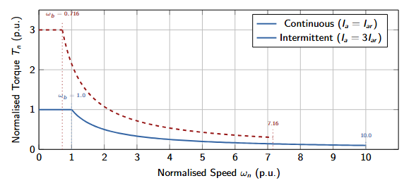
This is also the normalised base speed: \(\omega_{m1n} = e_n = 0.716\,\text{p.u.}\)

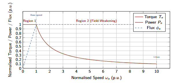
Field-weakening flux requirement

To maintain \(E_b = e_m\) at speed \(\omega_{mn}\):

\[ \phi_{fn} = \frac{e_n}{\omega_{mn}} = \frac{0.716}{\omega_{mn}} \]

Normalised torque in Region 2

\[ T_{en} = I_{an}\cdot\phi_{fn} = 3 \times \frac{0.716}{\omega_{mn}} = \frac{2.148}{\omega_{mn}} \]

Maximum intermittent speed

Flux limit is the same: \(\phi_{\min} = 0.1\,\text{p.u.}\)

\[ \begin{aligned} \omega_{mn,\max} &= \frac{e_n}{\phi_{\min}} \\ &= \frac{0.716}{0.1} \\ &= \mathbf{7.16\,\text{p.u.}} \\ \omega_{m,\max} &= 7.16 \times 137.56 \\ &= 984.9\,\text{rad/s} \end{aligned} \]
Region 2 Equations (Intermittent, \(0.716 < \omega_n \leq 7.16\))
\[\phi_{fn} = \frac{0.716}{\omega_{mn}}\] \[T_{en} = \frac{2.148}{\omega_{mn}}\] \[P_e = T_e\,\omega_m = 3\times0.716 = 2.148\,\text{p.u.}\quad\text{(const.)}\]
Speed Range Reduction
Intermittent field weakening extends only to 7.16 p.u. (vs. 10 p.u. for continuous), because the higher \(I_{\max}R_a\) drop reduces the available back-EMF at the base point, shifting the entire field-weakening region downward.
Verification of Power Constancy
\[ \begin{aligned} \text{At } \omega_{mn} &= 2\,\text{p.u.}: \\ \quad T_{en} & = \frac{2.148}{2} = 1.074\,\text{p.u.}, \\ P_n &= 1.074 \times 2 = 2.148\,\text{p.u.} \;\checkmark \\[2em] \text{At } \omega_{mn} &= 7.16\,\text{p.u.}: \\ \quad T_{en} &= \frac{2.148}{7.16} = 0.300\,\text{p.u.}, \\ P_n &= 0.300 \times 7.16 = 2.148\,\text{p.u.} \;\checkmark \end{aligned} \]
Torque–Speed Characteristic of DC Motor Drives Continuous vs. Intermittent
Torque–Speed Characteristic: Continuous vs. Intermittent

6. Summary of Results

Complete Parameter Tables

Continuous Operation Parameters
ParameterValue
Rated speed \(\omega_{mr}\)137.56 rad/s
Rated torque \(T_{er}\)14.23 N·m
Rated armature current \(I_{ar}\)18.63 A
Rated field current \(I_{fr}\)1.2 A
Rated back-EMF \(e_r\)105.1 V
Base speed1.0 p.u.
Maximum speed10.0 p.u.
Minimum flux \(\phi_{\min}\)0.1 p.u.
Intermittent Parameters (300% \(I_a\))
ParameterValue
Peak current \(I_{\max}\)55.89 A (3 p.u.)
Peak torque \(T_{e,\max}\)42.70 N·m (3 p.u.)
Peak back-EMF \(e_m\)75.29 V (0.716 p.u.)
Intermittent base speed0.716 p.u. (98.54 rad/s)
Maximum speed7.16 p.u.
Minimum flux \(\phi_{\min}\)0.1 p.u. (same)
Const. power (Region 2)2.148 p.u.

Operating Regions — Complete Summary

Region Speed Range (p.u.) Torque \(T_n\) Power \(P_n\) Flux \(\phi_{fn}\)
1 — Continuous 0 → 1.0 1.0 (constant) \(\omega_n\) (increasing) 1.0 (constant)
2 — Continuous 1.0 → 10.0 \(1/\omega_n\) (hyperbolic) 1.0 (constant) \(1/\omega_n\)
1 — Intermittent 0 → 0.716 3.0 (constant) \(3\omega_n\) (increasing) 1.0 (constant)
2 — Intermittent 0.716 → 7.16 \(2.148/\omega_n\) (hyperbolic) 2.148 (constant) \(0.716/\omega_n\)
Intermittent vs. Continuous — Key Differences
  • Torque: 3× higher (42.7 vs 14.23 N·m)
  • Base speed: lower (0.716 vs 1.0 p.u.) due to larger \(I_{\max}R_a\) drop
  • Max speed: reduced (7.16 vs 10.0 p.u.) — same \(\phi_{\min}\) but lower \(e_n\)
  • Field-weakening range: 0.716 to 7.16 p.u. (ratio = 10:1) vs 1.0 to 10.0 p.u. (ratio = 10:1) — same ratio, shifted lower
Torque–Speed Equations

Continuous Region 1 (\(0 \leq \omega_n \leq 1\)):

\[T_n = 1\,\text{p.u.}\]

Continuous Region 2 (\(1 \leq \omega_n \leq 10\)):

\[T_n = \frac{1}{\omega_n}\]

Intermittent Region 1 (\(0 \leq \omega_n \leq 0.716\)):

\[T_n = 3\,\text{p.u.}\]

Intermittent Region 2 (\(0.716 \leq \omega_n \leq 7.16\)):

\[T_n = \frac{2.148}{\omega_n}\]