By the end of this lecture, you will be able to:
Identify and explain the five main functional blocks of an electric drive system
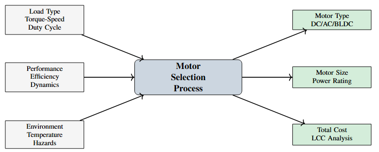
Understand the component selection strategy for drive design
Compare different types of electric motors and their characteristics
Distinguish between AC and DC power sources
Apply motor-load matching principles for practical applications
Drive System Architecture
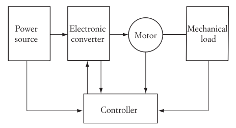
The Five Essential Components
Power Source: Electrical energy supply (AC/DC, fixed/variable)
Power Converter: Power electronic interface for control
Electric Motor: Electromechanical energy conversion
Mechanical Transmission: Coupling and speed/torque adjustment
Mechanical Load: The driven equipment/process
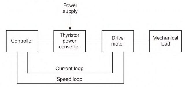
Key Addition: Control System
Sensors provide feedback (speed, position, current, voltage)
Controller processes signals and generates commands
Closed-loop operation ensures desired performance
Protection and diagnostic features included
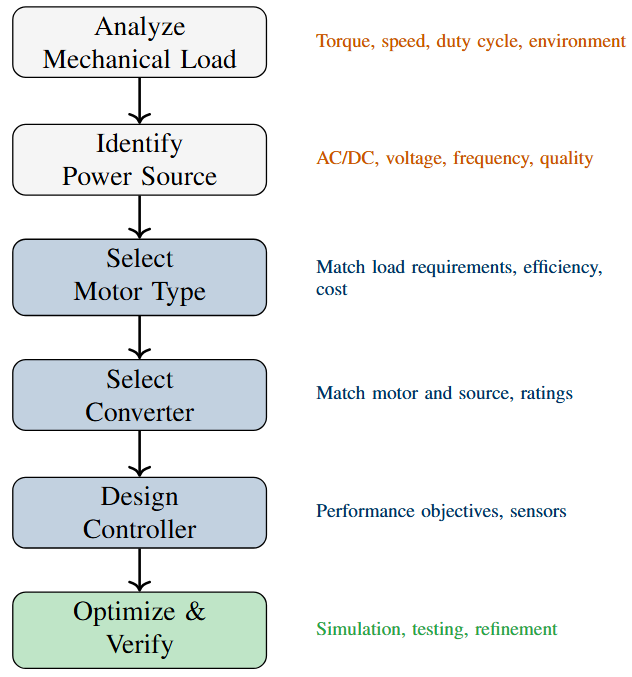
Typically Predetermined:
Mechanical Load
Determined by application
Torque-speed requirements
Duty cycle
Environmental conditions
Power Source
Determined by infrastructure
Grid availability
Voltage and frequency standards
Power quality
Designer Must Select:
Electric Motor
Type (DC, AC, synchronous, etc.)
Size and ratings
Speed-torque characteristics
Efficiency and power factor
Power Converter
Topology (rectifier, inverter, etc.)
Switching frequency
Ratings and protection
Controller
Control algorithm
Sensors and feedback
Processing platform
Electric Motors
Major Classifications
DC Motors
Separately excited, shunt, series, compound
Brushless DC (BLDC)
AC Motors
Induction motors (squirrel cage, wound rotor)
Synchronous motors (wound field, permanent magnet)
Special Purpose Motors
Stepper motors
Switched reluctance motors
Universal motors
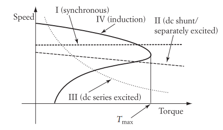
Curve I: Synchronous motor – constant speed
Curve II: DC shunt/separately excited – slight droop
Curve III: DC series – high torque at low speed
Curve IV: Induction motor – nearly constant speed with slip
Advantages:
Excellent speed control
High starting torque
Simple control (before VFDs)
Wide speed range
Four-quadrant operation
Fast dynamic response
Applications:
Traction (trains, metros)
Rolling mills
Paper machines
Cranes and hoists
Machine tools (legacy)
Disadvantages:
Commutator and brushes
Regular maintenance needed
Not suitable for dirty/explosive environments
Higher cost than induction
Limited speed (commutation)
Sparking issues
Modern Trend:
Being replaced by AC drives with VFDs
BLDC motors for brush-free operation
Still dominant in some legacy installations
| Parameter | Separately Excited | Shunt | Series | Compound |
|---|---|---|---|---|
| Speed regulation | Excellent | Good | Poor | Fair |
| Starting torque | Medium | Medium | Very High | High |
| Speed control | Excellent | Excellent | Limited | Good |
| No-load speed | Safe | Safe | Dangerous | Safe |
| Applications | Precise control | Constant speed | Traction | Variable loads |
| Cost | High | Medium | Low | Medium-High |
Selection Guideline
Series: High starting torque (cranes, traction)
Shunt: Constant speed (machine tools, fans)
Separately Excited: Precise control (rolling mills, paper machines)
Advantages:
Robust and reliable
Low cost and Minimal maintenance
Suitable for harsh environments
Self-starting
High efficiency (92-96%)
Available in wide power range
Types:
Squirrel Cage: Rugged, low cost, most common
Wound Rotor: Better starting, speed control via rotor resistance
Disadvantages:
Poor power factor at light loads
Limited speed control (without VFD)
Lower starting torque (squirrel cage)
Inrush current (5-7× rated)
Requires complex control for high performance
Applications:
Pumps and fans (60–70% of all motors)
Compressors, Conveyors, Process industries etc.
HVAC systems
Market Dominance
Over 90% of industrial motors are three-phase squirrel cage induction motors!
Characteristics:
Constant speed (synchronous with supply frequency)
Can operate at leading, lagging, or UPF
No slip losses and high efficiency
Requires DC excitation or permanent magnets
Types:
Wound Field: Adjustable excitation, large power
Permanent Magnet (PMSM): Compact, high efficiency
Advantages:
Power factor correction capability
High efficiency at all loads
Constant speed under varying loads
Suitable for low-speed, high-torque
Applications:
Large compressors
Ball mills, rubber and paper mills
Power factor improvement
Electric vehicles (PMSM)
Servo systems
Challenge
Not self-starting – requires starting mechanism or VFD for variable speed operation
Construction:
Permanent magnet rotor
Electronically commutated stator
Hall effect sensors for position
Requires electronic controller
Advantages:
No brushes (maintenance-free)
High efficiency (85-90%)
High power density
Low electromagnetic interference
Long life and better heat dissipation
Disadvantages:
Higher initial cost
Complex control required
Permanent magnet cost
Limited high-temperature operation
Applications:
Electric vehicles
Computer hard drives
HVAC fans
Drones and quadcopters
Power tools, medical equipment, aerospace actuation etc.
Growing Market
BLDC motors are the fastest growing segment, especially in automotive and consumer electronics.
| Aspect | DC (Brushed) | Induction | Synchronous | BLDC/PMSM |
|---|---|---|---|---|
| Cost | Medium | Low | Medium-High | High |
| Efficiency | 75–85% | 85–96% | 90–97% | 85–95% |
| Maintenance | High | Low | Low-Medium | Very Low |
| Speed control | Excellent | Good (VFD) | Excellent | Excellent |
| Power factor | N/A | 0.7–0.9 (lag) | Adjustable | 0.95+ |
| Starting torque | High | Low-Medium | Low | High |
| Ruggedness | Medium | Very High | High | High |
| Typical power | 0.1–1000 kW | 0.1–10+ MW | 100 kW–100 MW | 0.01–500 kW |
| Market share | Declining | Dominant (70%) | Growing | Fast growing |
Key factors to consider:
Load Requirements:
Torque-speed profile, starting torque, duty cycle
Performance:
Efficiency, power factor, speed range, dynamic response
Environmental:
Temperature, humidity, dust, explosive atmosphere
Economic:
Initial cost, operating cost, maintenance, life cycle cost
Practical:
Availability, standardization, compatibility with existing systems
| Application Requirement | Preferred Motor Choice |
|---|---|
| High starting torque, traction | DC series or PMSM with VFD |
| Constant speed, 24/7 operation | Synchronous motor |
| Variable speed, low cost, rugged | Squirrel cage induction + VFD |
| Precise positioning, servo | BLDC or PMSM with encoder |
| Harsh environment, simple control | Squirrel cage induction (DOL) |
| High power density, efficiency | Permanent magnet synchronous |
| Power factor correction needed | Synchronous motor (over-excited) |
| Clean room, maintenance-free | BLDC or sealed induction |
| Wide speed range, dynamic | Separately excited DC or PMSM |
General Guideline
When in doubt: Start with three-phase squirrel cage induction motor + VFD – it covers 80% of applications!
Power Sources
Two Main Categories
Alternating Current (AC) Sources
Single-phase AC
Three-phase AC
Variable frequency AC (rare)
Direct Current (DC) Sources
Batteries
Solar photovoltaic systems
Fuel cells
DC microgrids
Rectified AC (most common industrial DC)
Single-Phase AC:
Voltage: 120V/240V (US), 230V (Europe/India)
Frequency: 60 Hz or 50 Hz
Applications:
Residential and small commercial
Motors up to ~3 kW
Limitations:
Pulsating torque
Lower power capacity
Starting issues
Three-Phase AC:
Voltage: 208V, 480V, 4160V, etc. (US)
400V, 690V, 11kV, etc. (International)Frequency: 50/60 Hz standard
Applications:
Industrial facilities
Commercial buildings
All power levels
Advantages:
Constant power, and better efficiency
Self-starting motors and balanced loading
Standard
Industrial drives almost exclusively use three-phase AC as the primary power source.
| Category | Voltage Range | Typical Values | Applications |
|---|---|---|---|
| Low Voltage | Up to 1 kV | 208V, 240V, 480V, 690V | Most industrial drives |
| Medium Voltage | 1–35 kV | 2.3 kV, 4.16 kV, 11 kV | Large drives (>1 MW) |
| High Voltage | Above 35 kV | 66 kV, 132 kV, 220 kV | Transmission (not drives) |
| India Standards: | |||
| Single-phase | 230 V | 230V ± 10% | Residential |
| Three-phase (LV) | 400 V | 400V ± 10% | Commercial/Industrial |
| Three-phase (MV) | 11 kV, 33 kV | Large facilities | |
Important
Motor and converter ratings must match the available power supply voltage and frequency!
Battery Systems:
Types: Lead-acid, Li-ion, NiMH, etc.
Voltages: 12V, 24V, 48V (automotive)
200–800V (EVs), 270V (aircraft)Applications:
Electric vehicles
Material handling (forklifts)
Backup power (UPS)
Portable equipment
Advantages:
Energy storage
Portable
Clean power
Other DC Sources:
Solar PV:
Variable DC output
Requires MPPT converter
Growing in solar pumping
Fuel Cells:
Clean hydrogen-to-electricity
Limited to specialized applications
Rectified AC:
Most common industrial DC
Controlled or uncontrolled rectification
Challenges:
Energy density (weight)
Charging time, Cost, and Life cycle
Large facilities maintain complex power distribution:
Typical Configuration:
Utility connection (MV)
Main transformer(s)
Multiple voltage levels:
11 kV or 6.6 kV distribution
690V or 400V for drives
230V for lighting/control
Emergency generators
UPS systems for critical loads
Power factor correction
Special Systems:
Aircraft:
400 Hz, 3-phase AC
270V DC bus
28V DC (legacy)
Ships:
440V, 60 Hz typical
DC distribution for propulsion
Railways:
25 kV AC overhead (India)
1500V DC or 3000V DC
Data Centers:
380V DC distribution (emerging)
Higher efficiency
Important power source characteristics:
Voltage Regulation:
Variation should be within ±10%
Affects motor performance and converter operation
Frequency Stability:
Critical for synchronous motors
Should be within ±1% for most applications
Harmonics:
Power electronic loads introduce harmonics
Total Harmonic Distortion (THD) should be <5%
Requires filtering and power factor correction
Power Factor:
Industrial target: PF > 0.95
Affects utility charges
Modern drives include PF correction
Motor-Load Matching
Why Matching Matters
Proper motor-load matching ensures:
Optimal efficiency and performance
Minimum energy consumption
Reliable operation
Maximum equipment life
Cost-effectiveness
Poor Matching Consequences
Oversized motor: Higher initial cost, lower efficiency at partial load, poor power factor
Undersized motor: Overheating, frequent trips, reduced life, inability to handle peak loads
Wrong motor type: Poor starting, inefficient operation, control difficulties
Speed Requirements:
Constant speed needed:
Synchronous motor (best)
Induction motor (good)
DC shunt with feedback
Variable speed:
Induction + VFD
DC separately excited
PMSM + controller
Positioning:
Servo motors (BLDC/PMSM)
Stepper motors
Torque Requirements:
High starting torque:
DC series
Wound rotor induction
PMSM with VFD
Constant torque load:
DC shunt
Induction + VFD
Variable torque (fan):
Squirrel cage induction
Energy savings with VFD
Environmental Constraints:
Clean environments:
Food, pharmaceutical, aerospace
No brushes (BLDC, induction)
Sealed enclosures
Hazardous locations:
Explosion-proof motors
Special cooling
Intrinsically safe circuits
Outdoor/harsh:
IP55/IP65 enclosures
Corrosion protection
Temperature ratings
Cost Hierarchy:
Initial cost:
Lowest: Squirrel cage induction
Medium: DC, wound rotor
Highest: PMSM, servo motors
Operating cost:
Energy consumption
Maintenance requirements
Downtime costs
Life cycle cost:
Total cost over 10-20 years
Often energy dominates
VFD pays back quickly
Application: Water pumping, 24/7 operation, variable demand
Load Characteristics:
Power ∝ speed3 (fan law)
Torque ∝ speed2
Unidirectional
Frequent speed changes
Power Source:
3-phase, 400V, 50 Hz
Grid connected
Motor Selection:
Best Choice: Squirrel cage induction + VFD
Rating: Based on maximum flow requirement
Energy class: IE3 or better
Justification:
Lowest cost solution
High reliability
VFD enables huge energy savings
Simple maintenance and Proven technology
Energy Savings
Running at 80% speed reduces power by 50%! VFD payback: 6-18 months.
Application: Precision machining, positioning accuracy ±0.01 mm
Load Characteristics:
Multiple axes (X, Y, Z, spindle)
Bidirectional operation
Precise positioning required
Fast dynamic response
Variable cutting loads
Power Source:
3-phase, 400V, 50 Hz
Clean, stable supply
Motor Selection:
Axes: PMSM servo motors with encoders
Spindle: Induction motor + VFD
Justification:
Servo motors: High precision, fast response
Encoders: Position feedback
Spindle: Variable speed, high power
Four-quadrant capability
Critical
High-performance applications justify premium motor costs for required precision and dynamic performance.
Application: Passenger elevator, 10 floors, frequent starts/stops
Load Characteristics:
Constant torque (hoisting)
Four-quadrant operation
Regenerative braking needed
High starting torque
Smooth acceleration/deceleration
Requirements:
Comfort (low jerk)
Safety (reliable braking)
Energy efficiency and Low noise
Motor Selection:
Modern: PMSM gearless traction
Traditional: Induction + gearbox + VFD
Justification:
PMSM: Compact, efficient, gearless
Regeneration: Returns energy to grid
VFD: Smooth control, energy savings
Modern trend: PMSM replacing geared systems
Trend
PMSM gearless elevators: 30-50% more efficient, quieter, more compact than traditional systems.
Summary and Preview
Five functional blocks: Power source, converter, motor, transmission, load – with controller providing intelligence
Component selection: Load and source are predetermined; designer selects motor, converter, and controller
Motor types: Each has advantages/disadvantages
Induction: Workhorse (70% market share)
DC: Excellent control but maintenance
Synchronous: Constant speed, PF control
BLDC/PMSM: High performance, growing rapidly
Power sources: Three-phase AC dominates industrial; DC for mobile/specialized
Motor-load matching: Critical for efficiency, reliability, and cost-effectiveness
Key Principle
There's no single "best" motor – selection depends on application requirements, constraints, and trade-offs.