Introduction to Thyristor Commutation
What is Thyristor Commutation?
Definition
Commutation is the process of turning OFF a conducting thyristor by reducing the anode current below the holding current level.
Key Characteristics:
-
Thyristors can be turned ON by gate signal but cannot be turned OFF by gate signal
-
Once triggered ON, they remain conducting until commutated
-
Commutation is essential for controlled switching in power circuits
-
Different techniques are used for different applications
Importance of Commutation
Why is commutation critical?
- Control:
-
Enables precise control of power flow in circuits
- Protection:
-
Prevents damage from overcurrent conditions
- Circuit Operation:
-
Essential for proper functioning of converters
- Flexibility:
-
Allows various circuit configurations and applications
Key Point
Without proper commutation, thyristors cannot be used effectively in many power electronic applications.
Classification of Commutation Techniques
Commutation Methods Overview
Two Main Categories
-
Natural Commutation
-
Forced Commutation
Natural Commutation
-
Line commutation
-
Load commutation
Uses AC supply characteristics
Forced Commutation
-
Class A (Resonant)
-
Class B (LC Circuit)
-
Class C (Complementary)
-
Class D (Auxiliary)
-
Class E (External Pulse)
Uses external circuits
Natural Commutation
Natural Commutation Principles
Definition
Natural commutation occurs when the anode current naturally becomes zero due to AC supply conditions, without any external commutation circuit.
Operating Principle:
-
Makes use of the alternating nature of AC voltages
-
Current passes through zero every half cycle in AC circuits
-
When current becomes zero, reverse voltage appears across the thyristor
-
This reverse voltage turns OFF the thyristor
Applications
AC voltage controllers, rectifiers, cycloconverters
Types of Natural Commutation
-
Line Commutation:
-
Current zero occurs due to AC supply voltage reversal
-
Most common in rectifier circuits
-
Thyristor turns OFF when AC supply goes negative
-
-
Load Commutation:
-
Current zero occurs due to load circuit characteristics
-
Load impedance causes current to become zero
-
Less common than line commutation
-
Limitation
Only works with AC supply or oscillatory currents
Forced Commutation Techniques
Forced Commutation Overview
When is Forced Commutation Required?
-
DC circuits (choppers)
-
Inductive load circuits
-
Inverter circuits
-
When controlled turn-OFF is needed
Basic Principle:
-
Force the anode current below holding current
-
Apply reverse voltage across thyristor
-
Provide sufficient turn-off time (\(t_q\))
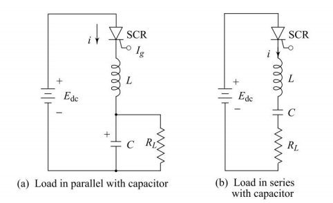
Class A - Resonant Commutation
Class A: Resonant Commutation circuit & Operation
Characteristics:
-
Also known as self commutation
-
Uses L-C components to create oscillatory current
-
Current oscillates and passes through zero
-
Also called current commutation method
Key Features:
-
Load forms part of resonant circuit
-
Current has sinusoidal/oscillatory nature
-
Automatic turn-OFF at current zero
Applications
High frequency applications (above 1000 Hz), series inverter circuits, oscillator circuits
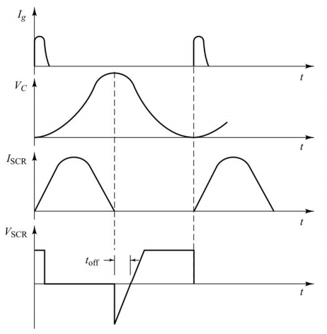
Class A: Operating Principle
Circuit Operation Sequence:
-
When thyristor is triggered, L-C-R circuit is excited by DC source
-
Current has oscillatory/sinusoidal nature due to L-C resonance
-
Current decreases to zero at some point
-
Thyristor automatically turns OFF at current zero
-
Beyond zero point, current tries to reverse but thyristor blocks it
Advantage
Simple and automatic commutation without external control
Class A: Voltage and Current Waveforms
Class B - LC Circuit Commutation
Class B: LC Circuit Commutation
Circuit Configuration:
-
LC resonant circuit is connected across the thyristor
-
Capacitor is initially charged to supply voltage
-
Load is separate from commutating circuit
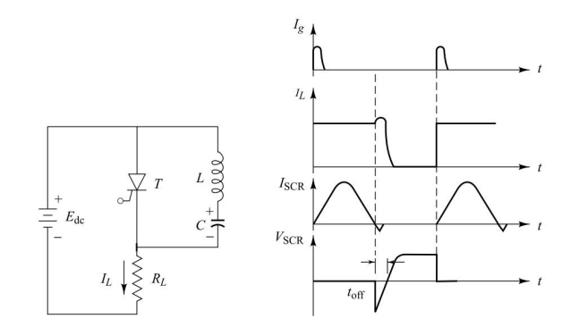
Operation Principle:
-
When thyristor is triggered, two currents flow:
-
Load current through load
-
Commutating current through LC circuit
-
-
Oscillatory current opposes load current
-
When commutating current exceeds load current, net current becomes zero
Class B: Design Requirements
Critical Design Requirement:
For successful commutation:
Turn-off time provided:
Applications
DC chopper circuits, applications where load and commutating circuits need to be separate
Class C - Complementary Commutation
Class C: Complementary Commutation Circuit & Operation
Circuit Elements:
-
Main thyristor (\(T_1\)) in series with load
-
Auxiliary thyristor (\(T_2\)) - complementary thyristor
-
Commutating capacitor (C)
-
Both thyristors share the same load current path
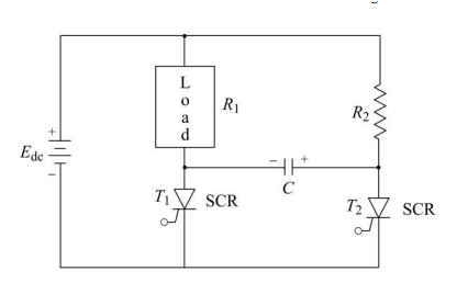
Key Features:
-
Uses pre-charged capacitor for commutation
-
Very reliable commutation method
-
Suitable for frequencies below 1000 Hz
-
Two thyristors operate alternately
Class C: Circuit Operation
Mode 1: \(T_1\) is triggered and conducting
-
Load current flows through \(T_1\)
-
Capacitor C charges to supply voltage through load and \(T_1\)
-
\(T_2\) is OFF
Mode 2: \(T_2\) is triggered for commutation
-
\(T_2\) turns ON
-
Charged capacitor applies reverse voltage to \(T_1\)
-
\(T_1\) gets reverse biased and turns OFF
-
Load current now flows through \(T_2\)
-
Capacitor voltage reverses
Result: \(T_1\) is successfully turned OFF and \(T_2\) takes over
Class C: Design Parameters
Turn-off time:
Capacitor Selection:
Applications
McMurray-Bedford inverter, AC motor drives, applications requiring reliable commutation
Class C: Voltage and Current Waveforms
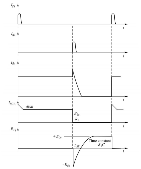
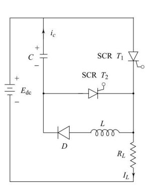
Class D - Auxiliary Commutation
Class D: Auxiliary Thyristor Commutation
Circuit Components:
-
Main thyristor (\(T_1\)) with load
-
Auxiliary thyristor (\(T_2\)) for commutation
-
Commutating inductor (L) and capacitor (C)
-
Diode (D) for proper circuit operation
Key Features:
-
Separate commutation circuit
-
Can transfer commutation energy back to load
-
Higher efficiency possible
-
More complex than Class C
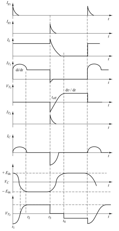
Class D: Operation Sequence
Step 1: Capacitor charging
-
\(T_2\) is triggered first
-
Capacitor C charges through: Supply \(\to\) C \(\to\) \(T_2\) \(\to\) Load
-
When fully charged, \(T_2\) turns OFF naturally
Step 2: Main thyristor operation
-
\(T_1\) is triggered, load current flows through \(T_1\)
-
Capacitor voltage reverses during discharge
Step 3: Commutation
-
To turn OFF \(T_1\), trigger \(T_2\) again
-
Reverse charged capacitor applies reverse voltage to \(T_1\)
Class D: Design Considerations
Basic Design Relations:
For turn-off time:
For successful commutation:
Applications
Jones chopper circuit, DC motor drives, applications requiring energy recovery
Class D: Voltage and Current Waveforms
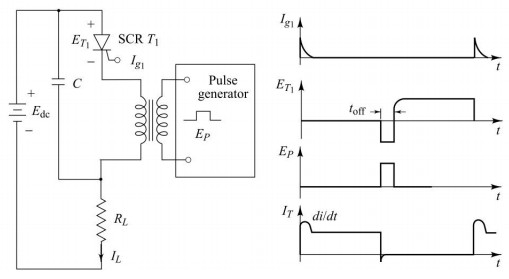
Class E - External Pulse Commutation
Class E: External Pulse Commutation Circuit & Operation
Principle:
-
Uses external pulse source for commutation
-
Pulse transformer provides isolation
-
Reverse voltage pulse applied to thyristor
-
Duration of pulse must exceed turn-off time
Advantages:
-
Very efficient
-
Simple control
-
Fast commutation
Disadvantages:
-
Additional pulse source
-
Critical transformer design
-
Less commonly used
Comparison and Selection
Comparison of Commutation Methods
| Parameter | Natural | Class A | Class B | Class C | Class D |
|---|---|---|---|---|---|
| Circuit Complexity | Low | Medium | Medium | Medium | High |
| Extra Components | None | L, C | L, C | C, SCR | L, C, SCR, D |
| Reliability | High | Medium | High | High | High |
| Efficiency | High | Medium | Medium | Medium | High |
| Cost | Low | Low | Medium | Medium | High |
| Applications | AC circuits | Oscillators | Choppers | Inverters | Choppers |
Selection Guidelines
Choose Natural Commutation when:
-
AC supply is available
-
Simple circuit is desired
-
Cost is a major factor
Choose Forced Commutation when:
-
DC supply is used
-
Controlled turn-OFF is needed
-
Inverter or chopper application
Key Selection Factors: Power level, load type, operating frequency, cost constraints, efficiency requirements
Applications in Power Electronics
Practical Applications
Natural Commutation:
-
AC voltage controllers
-
Phase-controlled rectifiers
-
Cycloconverters
-
AC motor soft starters
Class A Commutation:
-
Series resonant inverters
-
High-frequency oscillators
-
Induction heating
Class B & D:
-
DC choppers
-
DC motor drives
-
Battery chargers
-
SMPS circuits
Class C:
-
Voltage source inverters
-
UPS systems
-
AC motor drives
Design Example
Practical Design Example: Class B Commutation
Given Parameters:
-
Load current: \(I_L = 5\) A
-
Supply voltage: \(V_s = 50\) V
-
Required turn-off time: \(t_{off} = 50 \mu s\)
Design Approach:
From turn-off time requirement:
Therefore: \(\sqrt{LC} = 31.8 \times 10^{-6}\) s
For successful commutation (safety factor 1.5):
Design Example: Solution
Solving the Design equations:
Given constraints:
Solution:
-
Inductor: \(L = 31.8 \times 10^{-6} \times 6.67 = 212 \mu H\)
-
Capacitor: \(C = \dfrac{31.8 \times 10^{-6}}{6.67} = 4.77 \mu F\)
Standard Values:
-
\(L = 220 \mu H\)
-
\(C = 4.7 \mu F\)
Verification
Turn-off time \(\approx 50 \mu s~\checkmark\) , Peak current \(> 7.5 A~\checkmark\)
Summary and Conclusion
Key Learning Points
Essential Concepts:
-
Commutation is essential for turning OFF thyristors
-
Natural commutation works only with AC supply
-
Forced commutation is needed for DC circuits and controlled applications
-
Different forced commutation classes suit different applications
-
Proper design ensures reliable thyristor operation
-
Selection depends on application requirements and constraints
Important Takeaway
Understanding commutation techniques is fundamental for designing thyristor-based power electronic circuits.
Final Remarks
Design Considerations:
-
Always ensure sufficient turn-off time (\(t_{off} \geq t_q\))
-
Consider safety margins in current ratings
-
Account for component tolerances
-
Verify thermal and voltage ratings
Future Trends:
-
Modern power devices (IGBTs, MOSFETs) offer gate turn-off capability
-
Thyristors still important for high-power, high-voltage applications
-
Understanding principles remains valuable for power electronics