Introduction to Rectifiers
What is Rectification?
Definition
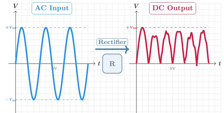
Rectification converts alternating current (AC) to direct current (DC) using semiconductor devices such as diodes or thyristors.
-
Essential component in DC power supplies
-
Used in applications requiring DC power from AC mains
Types of Rectifiers and Need for Three-Phases
Types of Rectifiers
-
Uncontrolled: Diodes only (fixed output)
-
Controlled: Thyristors/SCRs (variable output)
-
Half-Wave: Uses one half of AC cycle
-
Full-Wave: Uses both halves of AC cycle
Why Three-Phase?
-
Higher power capability
-
Smoother DC output (lower ripple)
-
Common in industrial applications
-
Better transformer utilization
Three-Phase System Advantages
Benefits:
-
Constant power flow
-
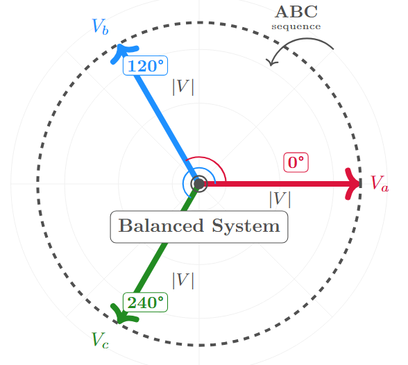
Balanced system
-
Higher efficiency
-
Reduced harmonics
-
Better regulation
Key Insight
Three-phase systems provide approximately \(\sqrt{3}\) times more power than single-phase for the same conductor material, making them ideal for industrial applications.
Why Three-Phase Rectifiers?
Advantages over Single-Phase:
-
Better transformer utilization factor
-
Lower ripple factor in output
-
Higher power handling capability
-
Better efficiency
-
Reduced harmonic content
Applications:
-
High-power DC motor drives
-
Battery chargers for large systems
-
DC power supplies for industrial applications
-
Electroplating and electrochemical processes
Three-Phase Half-Wave Uncontrolled Rectifier
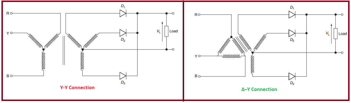
Circuit Configuration
Basic Circuit Components:
-
Three-phase transformer (star-connected secondary)
-
Three diodes (one per phase)
-
Load resistance \(R\)
-
Common neutral point required
Key Features:
-
Simplest three-phase rectifier configuration
-
Uses only three diodes
-
Natural commutation
-
Unidirectional current flow
Circuit Operation Principle
Operating Principle:
-
At any instant, the diode connected to the most positive phase conducts
-
Only one diode conducts at a time
-
Current flows through the conducting diode and load
-
Non-conducting diodes are reverse-biased
Conduction Sequence:
-
Phase R: \(30^{\circ} \leq \omega t \leq 150^{\circ}\)
-
Phase Y: \(150^{\circ} \leq \omega t \leq 270^{\circ}\)
-
Phase B: \(270^{\circ} \leq \omega t \leq 390^{\circ}\) (next cycle)
Each diode conducts for \(120^{\circ}\) in each cycle.
Voltage and Current Waveforms
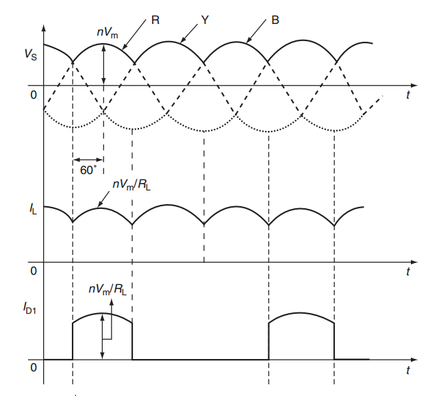
Key Observations:
-
Output voltage is pulsating DC
-
Three pulses per cycle (ripple frequency = \(3f\))
-
Continuous current through load (for resistive load)
Mathematical Analysis
Input Phase Voltages
For a balanced three-phase system with star-connected secondary:
Where:
-
\(V_m\): Peak value of phase voltage
-
\(\omega\): Angular frequency ( \(2\pi f\))
-
\(f\): Supply frequency
RMS Phase Voltage:
Output Voltage Analysis
The output voltage \(v_o\) follows the most positive input voltage:
Average Output Voltage:
Average Output Voltage (continued)
Since \(V_m = \sqrt{2} V_{ph}\), where \(V_{ph}\) is the RMS phase voltage:
For line voltage \(V_L = \sqrt{3} V_{ph}\) (star connection):
Alternative Expression:
RMS Output Voltage
The RMS value of output voltage:
Using the identity \(n^2(\omega t) = \frac{1 - \cos(2\omega t)}{2}\):
After integration:
Load Current Analysis
For resistive load \(R\):
Average Load Current:
RMS Load Current:
Peak Load Current:
Average Diode Current:
Performance Parameters
Ripple Factor
Ripple factor quantifies the AC content in DC output:
For three-phase half-wave rectifier:
Therefore, \(RF \approx 18.3\%\)
This is significantly lower than single-phase rectifiers (\(RF = 121\%\) for half-wave).
Form Factor and Peak Factor
Form Factor (FF):
Peak Factor (Crest Factor):
Comparison with Ideal DC:
-
Ideal DC: \(FF = 1\), \(CF = 1\)
-
Three-phase half-wave: \(FF = 1.016\), \(CF = 1.19\)
-
Indicates very good DC characteristics
Transformer Utilization Factor
TUF measures how effectively the transformer is utilized:
For three-phase half-wave rectifier:
Where \(I_{ph(rms)} = \frac{I_{rms}}{\sqrt{3}}\) (since each phase conducts for 120°)
Efficiency
Rectification Efficiency:
Contributing Factors:
-
No power loss in ideal diodes
-
Purely resistive load
-
Good waveform quality
Practical Considerations:
-
Diode forward voltage drop reduces efficiency
-
Transformer losses
-
Winding resistance
Practical Considerations
Diode Selection Criteria
Peak Inverse Voltage (PIV): Maximum reverse voltage across non-conducting diode occurs when one phase is at positive peak and others are at negative peaks.
In terms of line voltage: \(PIV = \frac{3}{\sqrt{2}} V_{ph} = \frac{3\sqrt{2}}{2} V_{ph} \approx 2.12 V_{ph}\)
Average Forward Current:
RMS Forward Current:
Transformer Design Considerations
Secondary Winding:
-
Must be star-connected for neutral point
-
Each phase carries current for \(120^{\circ}\) per cycle
-
RMS current in each phase: \(I_{ph} = \frac{I_{rms}}{\sqrt{3}}\)
Primary Winding:
-
Can be star or delta connected
-
Carries discontinuous current
-
Contains harmonics due to non-sinusoidal secondary current
Transformer Rating:
Harmonic Analysis
The output voltage contains harmonics at frequencies \(3nf\) (where \(n = 1, 2, 3, \dots\)):
Fourier Series:
Dominant Harmonics:
-
3rd harmonic (150Hz for 50Hz supply)
-
6th harmonic (300Hz for 50Hz supply)
-
9th harmonic (450Hz for 50Hz supply)
Filtering Requirements:
-
Low-pass filter with cutoff below 150Hz
-
Inductor-capacitor (LC) filters commonly used
-
Filter design based on acceptable ripple level
Load Types and Effects
Resistive Load (R):
-
Continuous current flow
-
Current waveform follows voltage waveform
-
Simple analysis
Inductive Load (R-L):
-
Current more continuous
-
Reduced ripple in current
-
Freewheeling diodes may be needed
-
Complex analysis required
Capacitive Load (R-C):
-
Capacitor provides filtering action
-
Discontinuous diode currents
-
Higher peak currents
-
Better voltage regulation
Advantages and Disadvantages
Advantages
-
Simple Circuit: Only three diodes required
-
Low Ripple: 18.3% vs 121% for single-phase
-
High Efficiency: Theoretical efficiency of 96.9%
-
Good TUF: Better transformer utilization than single-phase
-
Natural Commutation: No external switching control needed
-
Cost Effective: Fewer components than full-wave rectifiers
-
Reliable: Simple design enhances reliability
Disadvantages
-
Neutral Point Required: Transformer secondary must be star-connected
-
Transformer Utilization: TUF could be better
-
Unbalanced Transformer: Secondary neutral carries current
-
PIV Rating: Diodes need reasonable reverse voltage rating
-
Harmonics: Input current contains harmonics
-
Limited Power: Lower power capability than full-wave
-
DC Magnetization: Transformer core may saturate due to DC component
Applications
Typical Applications
Industrial Applications:
-
Battery charging systems
-
DC motor drives (low to medium power)
-
Electroplating processes
-
DC welding power supplies
Commercial Applications:
-
UPS systems (charging circuit)
-
LED lighting drivers
-
Telecommunications power supplies
-
Electric vehicle charging stations
Laboratory Applications:
-
Variable DC power supplies
-
Electronic equipment testing
-
Research and development projects
Design Example
Design Problem: Design a three-phase half-wave rectifier with:
-
Input: 3-phase, 415V line voltage, 50Hz
-
Output: 200V DC, 10A DC current
-
Load: Resistive
Solution Steps:
-
Calculate required transformer secondary line voltage
-
Determine diode ratings (PIV, current)
-
Calculate transformer ratings
-
Design output filter (if required)
-
Verify performance parameters
Design Example - Solution
Given: \(V_L = {415}{\mathrm{V}}\), \(V_{dc} = {200}{\mathrm{V}}\), \(I_{dc} = {10}{\mathrm{A}}\)
Step 1: Check if given line voltage is suitable
Required Secondary Line Voltage:
Step 2: Transformer turns ratio
Step 3: Diode ratings
-
Average forward current: \(I_{F(avg)} = \frac{I_{dc}}{3} = \frac{10}{3} \approx {3.33}{\mathrm{A}}\)
-
Phase voltage: \(V_{ph} = \frac{296}{\sqrt{3}} \approx {171}{\mathrm{V}}\)
-
Peak inverse voltage: \(PIV = 2.12 \times 171 \approx {362}{\mathrm{V}}\)
-
Select diodes: \(I_F \geq {5}{\mathrm{A}}\), \(V_R \geq {400}{\mathrm{V}}\)
Step 4: Load resistance
Step 5: Performance verification
-
Ripple factor: 18.3%
-
Efficiency: 96.9%
-
Form factor: 1.016
Comparison with Other Rectifiers
Comparison Table
| Parameter | 1-\(\phi\) Half | 3-\(\phi\) Half | 3-\(\phi\) Full |
|---|---|---|---|
| No. of diodes | 1 | 3 | 6 |
| Ripple factor (%) | 121 | 18.3 | 4.2 |
| Efficiency (%) | 40.6 | 96.9 | 99.5 |
| TUF | 0.287 | 0.675 | 0.955 |
| PIV | \(V_m\) | \(1.5 V_m\) | \(V_m\) |
| \(V_{dc}/V_m\) | 0.318 | 0.827 | 0.955 |
| Transformer neutral | Not required | Required | Not required |
Key Observations:
-
Three-phase half-wave significantly outperforms single-phase
-
Three-phase full-wave offers better performance but at higher cost
-
Choice depends on application requirements and cost constraints
Conclusion
Summary
Key Points Covered:
-
Circuit configuration and operation principle
-
Mathematical analysis of voltages and currents
-
Performance parameters (ripple factor, efficiency, TUF)
-
Practical design considerations
-
Advantages and disadvantages
-
Applications and design example
Learning Outcomes:
-
Understand three-phase rectification principles
-
Analyze and design three-phase half-wave rectifiers
-
Evaluate performance parameters
-
Apply to practical scenarios