Introduction
Need for Three-Phase Rectifiers
Limitations of Single-Phase Rectifiers
-
High ripple content in output voltage
-
Significant voltage variation with firing angle
-
Higher harmonic content requiring extensive filtering
-
Limited power handling capability
-
Poor power quality and low transformer utilization
Solution
Three-phase controlled rectifiers offer superior performance for medium to high power applications
Advantages of Three-Phase Controlled Rectifiers
Three-phase rectifiers provide:
Electrical Benefits:
-
Significantly reduced ripple voltage
-
Lower harmonic amplitude
-
Smoother DC output
-
Improved power factor
System Benefits:
-
Better transformer utilization
-
Higher power capability (\(>10 \, \mathrm{kW}\))
-
Reduced filter requirements
-
Cost-effective for industry
Ideal for high-power industrial applications
Industrial Applications
Motor Drives & Traction:
-
DC motor speed control
-
Variable speed drives
-
Railway traction systems
Power Systems:
-
HVDC transmission
-
Battery charging stations
Industrial Processes:
-
Electroplating
-
Electrolysis
-
Welding equipment
-
Manufacturing drives
Power Range
Typically \(>10 \, \mathrm{kW}\), extending to MW levels
Classification of Three-Phase Rectifiers
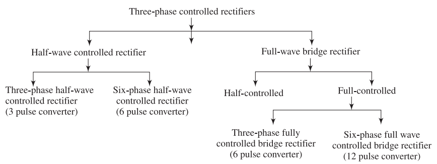
Classification Categories
By Configuration:
-
Half-wave (3-pulse, M-3)
-
Full-wave (6-pulse, M-6)
By Control Devices:
-
Fully controlled (all thyristors)
-
Semi-controlled (thyristors + diodes)
By Pulse Number:
-
3-pulse converter
-
6-pulse converter
-
12-pulse converter
Key Principle
Higher pulse number \(\Rightarrow\) Lower ripple and better performance
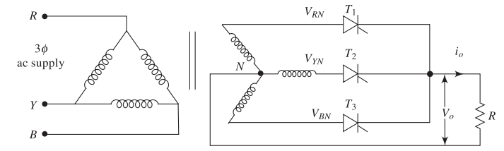
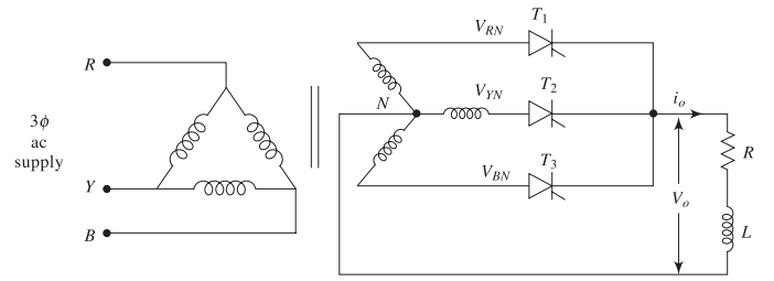
Three-Phase Half-Wave Controlled Rectifier
Circuit Configuration
Key Components:
-
Three thyristors: \(T_1\), \(T_2\), \(T_3\)
-
Three-phase transformer
-
Delta-connected primary
-
Star-connected secondary
-
-
Common neutral point N
-
Load between output and neutral
Designation: 3-phase, 3-pulse converter (M-3)
Three-Phase Voltage System
Balanced three-phase voltages:
Parameters:
-
\(V_m = \sqrt{2}V_{\text{ph}}\) – peak phase voltage
-
\(V_{\text{ph}}\) – RMS phase voltage
-
\(\omega = 2\pi f\) – angular frequency (rad/s)
-
Phase displacement: \(120^\circ\) or \(2\pi/3\) rad
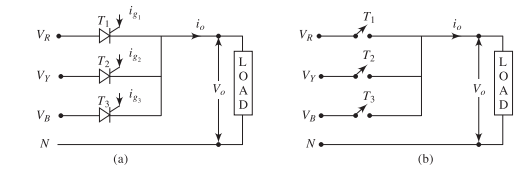
Principle of Operation
Operating Principle:
-
At any instant, the thyristor connected to the most positive phase is forward biased
-
When triggered, a thyristor conducts and connects its phase to the load
-
Natural commutation occurs when the next thyristor is fired
-
Load voltage follows the envelope of the most positive phase voltage
Operating Parameters
-
Firing sequence: \(T_1 \to T_2 \to T_3 \to T_1\) (repeats)
-
Firing interval: \(120^\circ\) between consecutive gate pulses
-
Conduction angle: \(120^\circ\) per thyristor (when \(\alpha \leq 30^\circ\))
Natural Commutation
Natural Commutation:
-
Occurs when incoming phase voltage exceeds conducting phase voltage
-
Conducting thyristor turns off automatically
-
Line commutation – no external circuit needed
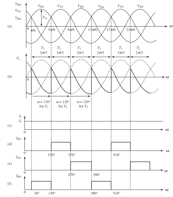
Commutation Points at \(\alpha = 0^\circ\):
-
\(T_1 \to T_2\): \(\omega t = 150^\circ\)
-
\(T_2 \to T_3\): \(\omega t = 270^\circ\)
-
\(T_3 \to T_1\): \(\omega t = 30^\circ\)
Operation with Resistive Load
Operating Modes with Resistive Load
-
Continuous Conduction Mode (CCM)
-
Condition: \(0^\circ \leq \alpha \leq 30^\circ\)
-
Each thyristor conducts for full \(120^\circ\)
-
Output voltage always positive
-
No gaps between conduction periods
-
-
Discontinuous Conduction Mode (DCM)
-
Condition: \(\alpha > 30^\circ\)
-
Conduction angle \(< 120^\circ\)
-
Output voltage periodically zero
-
Gaps appear between thyristor conductions
-
Continuous Conduction Mode Waveforms
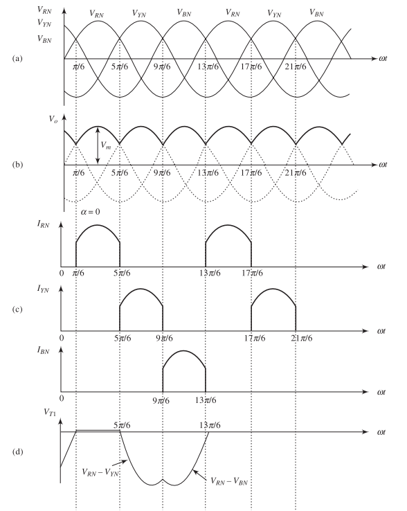
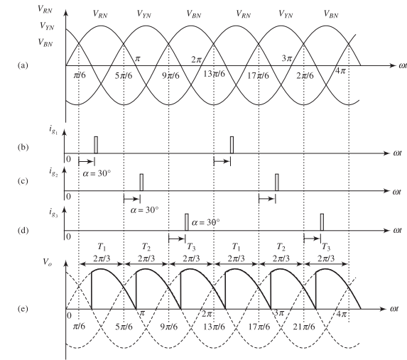
Features:
-
Three output pulses per AC cycle
-
Ripple frequency: \(3f\)
-
Each thyristor: \(120^\circ\) conduction
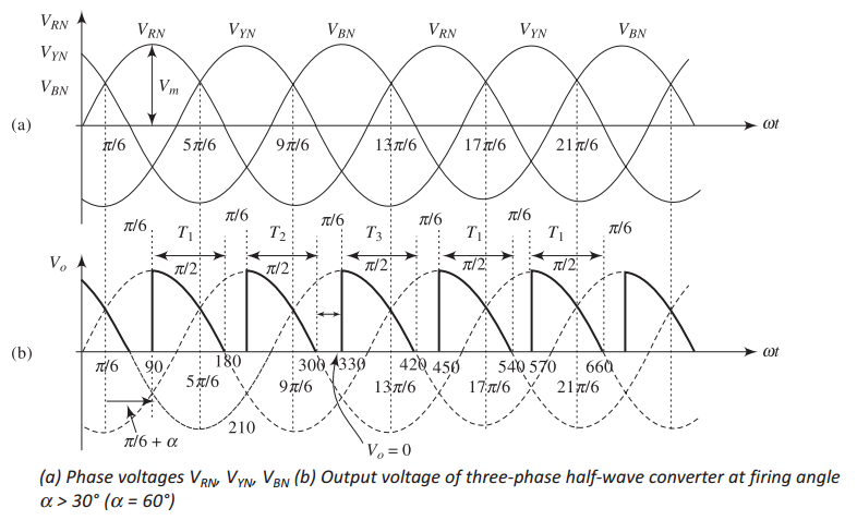
Discontinuous Conduction Mode Waveforms
Characteristics:
-
Conduction angle: \((150^\circ - \alpha)\)
-
Non-conduction period: \((\alpha - 30^\circ)\)
-
Discontinuous pulses with zero periods
Average DC Output Voltage
Continuous Conduction Mode (\(\alpha \leq 30^\circ\)):
Key Results
-
\(\boxed{V_{\text{dc}} = 0.827\,V_m\cos\alpha}\)
-
At \(\alpha = 0^\circ\): \(V_{\text{dc(max)}} = 0.827\,V_m = 1.17\,V_{\text{ph}}\)
Discontinuous Mode (\(\alpha > 30^\circ\)):
RMS Output Voltage
Continuous Conduction Mode (\(\alpha \leq 30^\circ\)):
Discontinuous Conduction Mode (\(\alpha > 30^\circ\)):
Important
Both \(V_{\text{dc}}\) and \(V_{\text{rms}}\) decrease as firing angle \(\alpha\) increases
Performance Parameters
Form Factor:
Ripple Factor:
Average Load Current (resistive load):
DC Output Power:
Rectification Efficiency:
Thyristor Current Ratings
For continuous conduction mode with resistive load:
Current Parameters
Average Thyristor Current:
RMS Thyristor Current:
Peak Thyristor Current:
Conduction Period: \(120^\circ\) or \(2\pi/3\) rad per thyristor
Operation with RL Load
Three-Phase Half-Wave with RL Load
Key Differences:
-
Inductance maintains continuous current flow
-
Load current cannot change instantaneously
-
Higher firing angles possible (up to \(150^\circ\))
-
Enables inverter mode (\(\alpha > 90^\circ\))
-
\(120^\circ\) conduction over wide \(\alpha\) range
Operating Ranges with RL Load
Range 1: \(0^\circ \leq \alpha \leq 30^\circ\)
-
Continuous conduction naturally maintained
-
Similar to resistive load behavior
Range 2: \(30^\circ < \alpha < 90^\circ\) (Rectifier Mode)
-
Modified rectifier operation
-
Output has negative portions, but \(V_{\text{dc}} > 0\)
-
Inductance maintains current continuity
Range 3: \(90^\circ < \alpha < 150^\circ\) (Inverter Mode)
-
Average voltage negative: \(V_{\text{dc}} < 0\)
-
Power flows from DC to AC supply
-
Requires DC voltage source (e.g., back EMF)
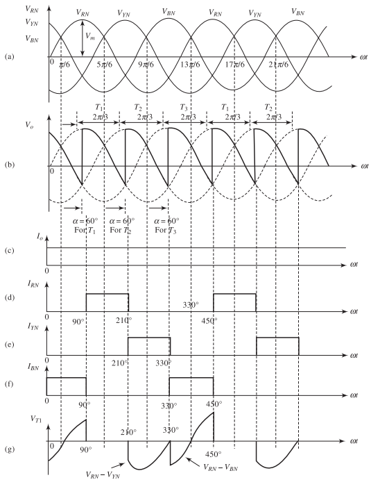
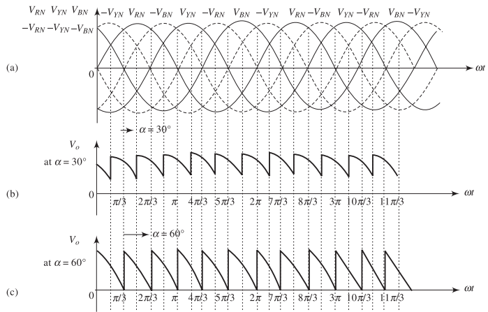
Waveforms for RL Load: \(\alpha = 60^\circ\)
Observations:
-
Each thyristor: \(120^\circ\) conduction
-
Output voltage contains negative portions
-
Current remains continuous
-
Average voltage:
\[V_{\text{dc}} = 0.414\,V_m~\text{ (positive)}\]
Rectifier Mode: \(\alpha < 90^\circ\)
Characteristics:
-
Average output voltage positive: \(V_{\text{dc}} > 0\)
-
Power flows from AC supply to DC load
-
Energy delivered to the load
Average Output Voltage
Boundary Condition at \(\alpha = 90^\circ\):
Inverter Mode: \(90^\circ < \alpha < 150^\circ\)
Characteristics:
-
Average voltage negative: \(V_{\text{dc}} < 0\)
-
Power flows DC to AC (regeneration)
-
Requires DC voltage source
-
Used for regenerative braking
Voltage and Current Relations with RL Load
For highly inductive load (continuous current):
Average Output Voltage:
Average Load Current (with back EMF \(E\)):
For Pure Inductive Load (\(R \approx 0\))
-
Voltage equation: \(V_{\text{dc}} = E\)
-
Required firing angle: \(\alpha = \cos^{-1}\left(\dfrac{E}{0.827\,V_m}\right)\)
-
Conduction: \(120^\circ\) per thyristor when \(\alpha \leq 150^\circ\)
Circuit Improvements
Delta-Zigzag Transformer Connection
Problem
DC component flows through transformer secondary:
-
Causes core saturation
-
DC magnetization
-
Reduced efficiency
-
Increased losses
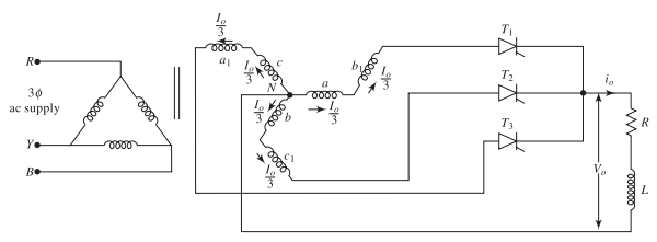
Delta-Zigzag Transformer – Working Principle
Construction:
-
Each secondary phase has two half-windings
-
Half-windings wound on different transformer legs
-
Connected in zigzag (interconnected-star) configuration
DC Component Cancellation:
-
Each half-winding carries \(I_{\text{dc}}/3\) DC current
-
Currents flow in opposite directions
-
Magnetic fluxes cancel each other
-
Net DC magnetization becomes zero
-
Prevents core saturation
Benefits
Improved transformer performance, efficiency, and reliability
Free-Wheeling Diode Configuration
Purpose of FWD:
-
Prevents negative output voltage
-
Alternative path for inductive current
-
Improves average voltage
-
Reduces PIV on thyristors
-
Improves load current waveform
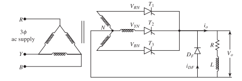
Operation with Free-Wheeling Diode
Operation (\(\alpha > 30^\circ\)):
-
FWD conducts when output tends negative
-
Thyristor conduction: \((150^\circ - \alpha)\)
-
FWD conduction: \((\alpha - 30^\circ)\) per cycle
-
Output clamped at zero
-
Current freewheels through FWD
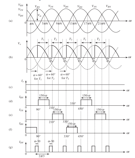
Output Voltage with Free-Wheeling Diode
Average DC Voltage (with FWD)
Note: Identical to discontinuous mode with resistive load
Current Ratings with FWD:
Average Thyristor Current:
Average FWD Current:
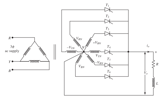
Six-Pulse Half-Wave Converter
Six-Pulse Half-Wave Converter Circuit
Configuration:
-
Six-phase star secondary
-
Six thyristors (one per phase)
-
Phase displacement: \(60^\circ\)
-
Designated M-6 converter
Advantages of Six-Pulse Converter
Compared to 3-pulse:
Advantages:
-
Six pulses per cycle
-
Lower ripple (\(f_r = 6f\))
-
Reduced filter requirements
-
Better TUF
-
Lower harmonic distortion
-
Easier commutation
Disadvantages:
-
Requires six-phase transformer
-
More complex construction
-
Higher number of thyristors
-
Increased cost
Six-Phase Voltage System
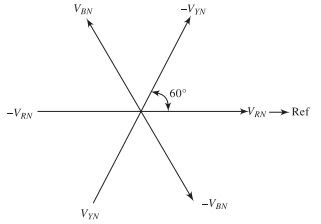
Phase Voltages (double-star configuration):
Principle of Operation
Operating Characteristics:
-
Each thyristor conducts for \(60^\circ\) (\(\pi/3\) rad)
-
Firing sequence: \(T_1 \to T_2 \to T_3 \to T_4 \to T_5 \to T_6 \to T_1\)
-
Firing interval: \(60^\circ\) between consecutive gate pulses
-
Output follows most positive phase voltage
-
Natural commutation every \(60^\circ\)
Output Voltage Equations
Average DC Output Voltage:
Key Result
\(\boxed{V_{\text{dc}} = 0.955\,V_m\cos\alpha}\) At \(\alpha = 0^\circ\): \(V_{\text{dc(max)}} = 0.955\,V_m = 1.35\,V_{\text{ph}}\)
RMS Output Voltage: \(V_{\text{rms}} = V_m\sqrt{\frac{1}{2\pi}\left[\frac{\pi}{6} + \frac{1}{2}\sin 60^\circ + \frac{1}{2}\sin 2\alpha\right]}\)
Ripple Frequency: \(f_{\text{ripple}} = 6f\) (300 Hz for 50 Hz supply)
Operating Modes of Six-Pulse Converter
With Resistive Load:
Continuous Conduction Mode
\(0^\circ \leq \alpha \leq 60^\circ\)
-
Each thyristor conducts for full \(60^\circ\)
-
No gaps in output voltage waveform
Discontinuous Conduction Mode
\(60^\circ < \alpha \leq 120^\circ\)
-
Conduction angle less than \(60^\circ\)
-
Gaps appear in output voltage
With RL Load: Continuous conduction maintained up to \(\alpha = 90^\circ\)
Thyristor Current Ratings
For continuous conduction with six-pulse converter:
Current Parameters
Average Thyristor Current: \(I_{T(\text{avg})} = \frac{I_{\text{dc}}}{6}\)
RMS Thyristor Current: \(I_{T(\text{rms})} = \frac{I_{\text{dc}}}{\sqrt{6}} = 0.408\,I_{\text{dc}}\)
Peak Inverse Voltage: \(\text{PIV} = 2V_m\)
Conduction Period: \(60^\circ\) or \(\pi/3\) rad per thyristor
Performance Comparison: 3-Pulse vs 6-Pulse
| Parameter | 3-Pulse (M-3) | 6-Pulse (M-6) |
|---|---|---|
| Number of thyristors | 3 | 6 |
| Conduction angle | \(120^\circ\) | \(60^\circ\) |
| Output pulses per cycle | 3 | 6 |
| Ripple frequency | \(3f\) | \(6f\) |
| \(V_{\text{dc}}\) at \(\alpha=0^\circ\) | \(0.827\,V_m\) | \(0.955\,V_m\) |
| \(I_{T(\text{avg})}\) | \(I_{\text{dc}}/3\) | \(I_{\text{dc}}/6\) |
| \(I_{T(\text{rms})}\) | \(I_{\text{dc}}/\sqrt{3}\) | \(I_{\text{dc}}/\sqrt{6}\) |
| Ripple factor | Higher | Lower |
| Filter size | Larger | Smaller |
6-pulse provides superior performance with lower ripple
Generalized m-Phase Converter
Generalized m-Phase Half-Wave Converter
Concept:
-
Extension of 3-pulse and 6-pulse converters
-
\(m\)-phase star-connected secondary winding
-
\(m\) thyristors (one per phase)
-
Phase displacement: \(360^\circ/m\)
General Characteristics
-
Each thyristor conducts: \(360^\circ/m\) or \(2\pi/m\) rad
-
Output pulses per cycle: \(m\)
-
Higher \(m\) \(\Rightarrow\) Smoother output and lower ripple
-
Ripple frequency: \(m \times f\)
Average Output Voltage – General Formula
For \(m\)-phase half-wave converter
\(\boxed{V_{\text{dc}} = \frac{m}{2\pi}V_m\sin\left(\frac{\pi}{m}\right)\cos\alpha}\)
Verification for specific cases:
-
\(m = 3\): \(V_{\text{dc}} = \dfrac{3}{2\pi}V_m\sin 60^\circ \cos\alpha = 0.827\,V_m\cos\alpha \quad \checkmark\)
-
\(m = 6\): \(V_{\text{dc}} = \dfrac{6}{2\pi}V_m\sin 30^\circ \cos\alpha = 0.955\,V_m\cos\alpha \quad \checkmark\)
-
\(m = 12\): \(V_{\text{dc}} = \dfrac{12}{2\pi}V_m\sin 15^\circ \cos\alpha = 0.988\,V_m\cos\alpha \quad \checkmark\)
RMS Output Voltage – General Formula
General expression for \(m\)-phase converter:
\(V_{\text{rms}} = V_m\sqrt{\frac{1}{2\pi}\left[\frac{\pi}{m} + \frac{1}{2}\sin\left(\frac{2\pi}{m}\right)\cos 2\alpha\right]}\)
Key Observations:
-
As \(m\) increases, \(V_{\text{rms}}\) approaches \(V_m\)
-
Ripple content decreases with increasing \(m\)
-
Form factor approaches unity for large \(m\)
-
Better power quality with higher pulse numbers
Current Ratings – General Formulas
For \(m\)-phase half-wave converter:
Current Parameters
Average Thyristor Current: \(I_{T(\text{avg})} = \frac{I_{\text{dc}}}{m}\)
RMS Thyristor Current: \(I_{T(\text{rms})} = \frac{I_{\text{dc}}}{\sqrt{m}}\)
Peak Thyristor Current: \(I_{T(\text{peak})} = \frac{V_m}{R}\)
Conduction Angle per Thyristor: \(\theta_c = \frac{2\pi}{m} \text{ rad} = \frac{360^\circ}{m}\)
Effect of Pulse Number on Performance
| Pulse No. (\(m\)) | 3 | 6 | 12 | 24 |
|---|---|---|---|---|
| \(V_{\text{dc}}/V_m\) at \(\alpha=0^\circ\) | 0.827 | 0.955 | 0.988 | 0.997 |
| Ripple frequency | \(3f\) | \(6f\) | \(12f\) | \(24f\) |
| Conduction angle | \(120^\circ\) | \(60^\circ\) | \(30^\circ\) | \(15^\circ\) |
| Filter size | Large | Medium | Small | Very Small |
| Relative ripple | High | Medium | Low | Very Low |
| Complexity | Low | Medium | High | Very High |
Trade-off
Higher pulse number provides better performance but increases system complexity and cost
Selection Criteria for Pulse Number
3-pulse converter:
-
Simple, low-cost applications
-
Low to medium power (\(<\) 10 kW)
6-pulse converter:
-
Most common for industry
-
Medium power (10–100 kW)
-
Good balance: performance vs. cost
12-pulse converter:
-
High power applications
-
HVDC transmission
-
Strict harmonic requirements
24-pulse converter:
-
Special applications
-
Very low harmonics required
Summary and Comparison
Comprehensive Comparison
| Parameter | 3-pulse | 6-pulse | \(m\)-pulse |
|---|---|---|---|
| Number of thyristors | 3 | 6 | \(m\) |
| Output pulses/cycle | 3 | 6 | \(m\) |
| Ripple frequency | \(3f\) | \(6f\) | \(mf\) |
| Conduction angle | \(120^\circ\) | \(60^\circ\) | \(360^\circ/m\) |
| \(V_{\text{dc}}\) at \(\alpha=0^\circ\) | \(0.827\,V_m\) | \(0.955\,V_m\) | \(\frac{m}{2\pi}V_m\sin\frac{\pi}{m}\) |
| \(I_{T(\text{avg})}\) | \(I_{\text{dc}}/3\) | \(I_{\text{dc}}/6\) | \(I_{\text{dc}}/m\) |
| \(I_{T(\text{rms})}\) | \(I_{\text{dc}}/\sqrt{3}\) | \(I_{\text{dc}}/\sqrt{6}\) | \(I_{\text{dc}}/\sqrt{m}\) |
| Filter requirement | Large | Medium | Small |
| Transformer | Simple | Center-tap | Complex |
| Cost | Low | Medium | High |
Key Performance Metrics Comparison
| Parameter | 3-pulse | 6-pulse |
|---|---|---|
| Avg. output voltage | \(1.17\,V_{\text{ph}}\) | \(1.35\,V_{\text{ph}}\) |
| Form factor | \(\approx 1.016\) | \(\approx 1.001\) |
| Ripple factor | \(\approx 0.18\) (18%) | \(\approx 0.04\) (4%) |
| Ripple frequency | 150 Hz @ 50 Hz | 300 Hz @ 50 Hz |
| Conduction/thyristor | \(120^\circ\) | \(60^\circ\) |
6-pulse: 4% ripple vs. 3-pulse: 18% ripple
Effect of Firing Angle on Output Voltage
Voltage-Angle Characteristic: \(V_{\text{dc}} = K\,V_m\cos\alpha\) where \(K = 0.827\) (3-pulse), \(K = 0.955\) (6-pulse)
Key Observations:
-
All converters follow \(\cos\alpha\) characteristic
-
Higher pulse \(\Rightarrow\) higher output voltage
-
Maximum voltage at \(\alpha = 0^\circ\)
-
Zero voltage at \(\alpha = 90^\circ\) (boundary)
-
Negative voltage (inverter) for \(\alpha > 90^\circ\) with RL load
-
Practical range: \(0^\circ \leq \alpha \leq 150^\circ\)
Advantages and Disadvantages
Advantages:
-
Simple topology
-
Natural commutation
-
Lower component count
-
Lower voltage stress
-
Bidirectional power flow
-
Cost-effective
Disadvantages:
-
DC component in transformer
-
Higher ripple vs. full-wave
-
Larger filter requirements
-
Unidirectional current
-
Limited to lower power
Industrial Applications
Three-Phase (3-pulse):
-
Battery charging systems
-
Electroplating processes
-
Simple DC power supplies
-
Low power DC motor drives
( \(<\) 10 kW)
Six-Phase (6-pulse):
-
Industrial DC motor drives
(10–100 kW) -
Controlled rectification
-
Better power quality needs
-
Medium power DC supplies
Note
For high power applications (\(>\) 100 kW), full-wave converters are generally preferred
Harmonics and Power Quality
Output Voltage Harmonics:
-
Dominant frequency: \(mf\) (where \(m\) is pulse number)
-
Harmonic orders: \(m, 2m, 3m, 4m, \ldots\)
-
Amplitude decreases with harmonic order
For 3-pulse: Harmonics at \(3f, 6f, 9f, 12f, \ldots\)
For 6-pulse: Harmonics at \(6f, 12f, 18f, 24f, \ldots\)
Input Current Harmonics:
-
Non-sinusoidal current from AC supply
-
Contains DC component (star secondary)
-
Triplen harmonics present (3rd, 9th, 15th)
-
Power factor decreases with increasing \(\alpha\)
-
Significant Total Harmonic Distortion (THD)
Transformer Considerations
1. DC Magnetization:
-
DC current flows through secondary windings
-
Causes core saturation and increased magnetizing current
-
Reduced efficiency and increased losses
-
Solution: Delta-zigzag transformer connection
2. Transformer Utilization Factor (TUF):
-
Lower than full-wave converters
-
Each secondary winding partially utilized
3. Rating Requirements:
-
Must handle DC component and harmonics
-
Voltage rating based on peak phase voltage
-
Current rating based on load and harmonic content
Key Takeaways
-
Half-wave converters use one thyristor per phase
-
Firing angle \(\alpha\) controls average output: \(V_{\text{dc}} \propto \cos\alpha\)
-
Higher pulse number \(\Rightarrow\) smoother output, lower ripple
-
Inductance maintains current continuity in RL loads
-
Delta-zigzag transformer eliminates DC magnetization
-
Free-wheeling diode prevents negative output voltage
-
Ripple frequency = (pulse number) \(\times\) supply frequency
-
Trade-off: performance vs. complexity/cost
-
Natural commutation simplifies control