Introduction
Introduction to Three-Phase Full-Wave Uncontrolled Rectifier
Definition
A three-phase full-wave uncontrolled rectifier converts three-phase AC to DC using diodes in a bridge configuration.
-
Utilizes six diodes arranged in two groups (positive and negative)
-
No control over output voltage; purely passive rectification
-
Also known as three-phase bridge rectifier or Graetz bridge
-
Widely used in industrial applications due to:
-
High efficiency (>95%)
-
Low ripple content (4.2%)
-
High power handling capability
-
Circuit Configuration
Circuit Diagram
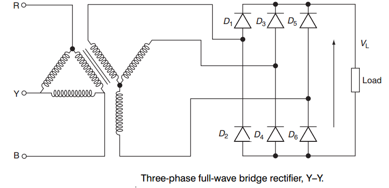
Working Principle
Working Principle
Conduction Sequence
Diodes conduct in pairs, with each pair conducting for \(120^{\circ}\)
-
Positive Group: \(D_1\), \(D_3\), \(D_5\) (connected to positive terminal)
-
Negative Group: \(D_2\), \(D_4\), \(D_6\) (connected to negative terminal)
-
At any instant, one diode from each group conducts
-
The diode with highest positive voltage in each group conducts
-
Conduction switches every \(60^{\circ}\)
of input cycle
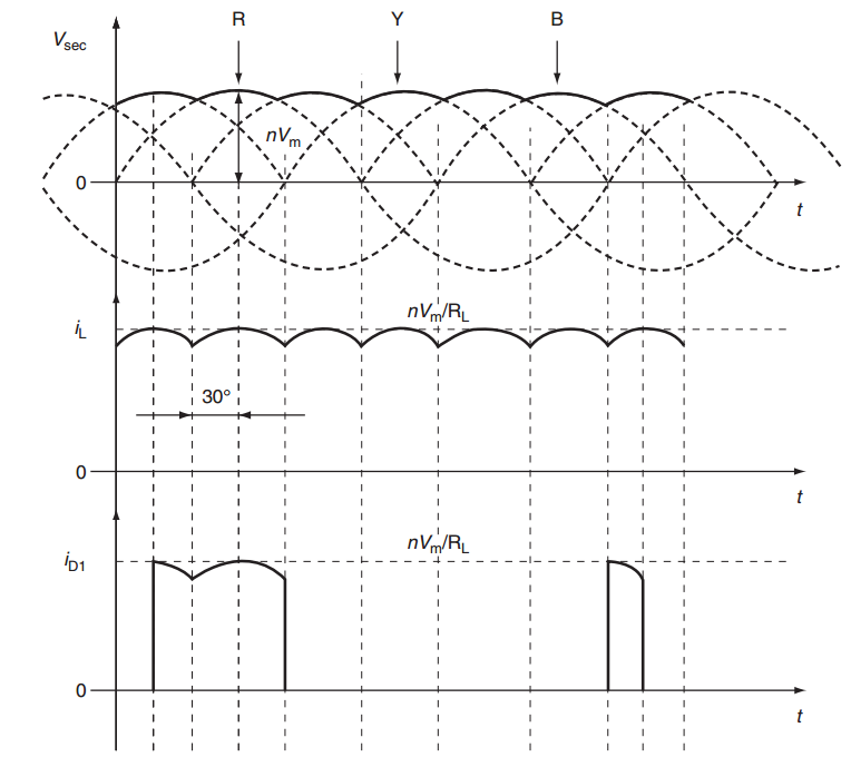
Key Point
Output is a pulsating DC with six pulses per AC cycle, resulting in low ripple content.
Conduction Intervals
| Interval | Angle Range | Conducting Diodes | Output Voltage |
|---|---|---|---|
| 1 | \(0^{\circ}\)to \(60^{\circ}\) | \(D_1\), \(D_6\) | \(V_a - V_c\) |
| 2 | \(60^{\circ}\)to \(120^{\circ}\) | \(D_1\), \(D_2\) | \(V_a - V_b\) |
| 3 | \(120^{\circ}\)to \(180^{\circ}\) | \(D_3\), \(D_2\) | \(V_b - V_a\) |
| 4 | \(180^{\circ}\)to \(240^{\circ}\) | \(D_3\), \(D_4\) | \(V_b - V_c\) |
| 5 | \(240^{\circ}\)to \(300^{\circ}\) | \(D_5\), \(D_4\) | \(V_c - V_b\) |
| 6 | \(300^{\circ}\)to \(360^{\circ}\) | \(D_5\), \(D_6\) | \(V_c - V_a\) |
Waveforms
Voltage and Current Waveforms
Mathematical Analysis
Mathematical Analysis - Input Voltages
Three-Phase Input Voltages
Line-to-Line Voltages
Mathematical Analysis - Output Parameters
Average (DC) Output Voltage
RMS Output Voltage
Ripple Factor
Performance Characteristics
Performance Characteristics
Key Metrics
-
Efficiency: > 95%
-
Ripple Factor: 4.2%
-
Form Factor: 1.0003
-
Crest Factor: 1.0003
-
Ripple Frequency: \(6f_{input}\)
Power Factor
-
Depends on load type
-
Resistive load: \(\cos\phi \approx 0.95\)
-
With smoothing inductor: Better PF but more complex
-
Input current contains harmonics
Load Regulation
Output voltage drops due to:
-
Diode forward voltage drop (\(\approx\) 0.7V per diode)
-
Source impedance
-
Commutation overlap (for inductive loads)
Advantages and Disadvantages
Advantages
-
High Efficiency: Minimal power loss in diodes (>95% efficiency)
-
Low Ripple: Only 4.2% ripple factor
-
High Power Capability: Suitable for high-power applications
-
Simple Design: No control circuitry required
-
Robust Operation: Reliable with minimal maintenance
-
Better Transformer Utilization: Compared to single-phase rectifiers
-
Lower Filter Requirements: Due to high ripple frequency
Disadvantages
-
No Voltage Control: Output voltage cannot be varied
-
Three-Phase Supply Required: Not always available
-
Higher Component Count: Six diodes required
-
Input Current Harmonics: May require filtering
-
Poor Power Factor: Especially with capacitive filtering
-
Commutation Problems: With inductive loads
-
Limited Flexibility: Cannot handle varying load requirements
Applications
Applications
Industrial Applications
-
DC motor drives
-
Electroplating systems
-
Welding equipment
-
Aluminum smelting
-
Electric arc furnaces
Power Systems
-
HVDC transmission systems
-
Battery charging stations
-
Renewable energy interfaces
-
UPS systems (front-end)
-
Railway traction systems
Selection Criteria
Choose three-phase rectifiers when:
-
Power rating > 5 kW
-
Three-phase supply is available
-
Low ripple content is required
-
High efficiency is important
Comparison with Other Rectifiers
Comparison with Other Rectifiers
| Parameter | \(1-\phi\) Half | \(1-\phi\) Full | \(3-\phi\) Half | \(3-\phi\) Full |
|---|---|---|---|---|
| Ripple Factor (%) | 121 | 48.2 | 18.3 | 4.2 |
| Efficiency (%) | 40.6 | 81.2 | 96.8 | >95 |
| TUF | 0.287 | 0.693 | 0.675 | 0.955 |
| PIV (per diode) | \(V_m\) | \(2V_m\) | \(\sqrt{3}V_m\) | \(\sqrt{3}V_m\) |
| No. of Diodes | 1 | 4 | 3 | 6 |
| Ripple Frequency | \(f\) | \(2f\) | \(3f\) | \(6f\) |
| Applications | Very Low Power | Low Power | Medium Power | High Power |
TUF = Transformer Utilization Factor, PIV = Peak Inverse Voltage
Design Considerations
Design Considerations
Diode Selection
-
Current Rating: \(I_F \geq 1.05 \times I_{dc}\) (for safety margin)
-
Voltage Rating: \(V_R \geq 2.45 \times V_{LL}\) (peak inverse voltage)
-
Surge Current: Consider inrush current capability
Thermal Management
-
Heat sink design for power dissipation
-
Junction temperature considerations
-
Forced cooling for high-power applications
Protection
-
Snubber circuits for voltage spikes
-
Fuses or circuit breakers for overcurrent protection
-
Surge arresters for transient protection
Conclusion
Conclusion
Summary
Three-phase full-wave uncontrolled rectifiers are essential power electronic devices offering:
-
Excellent Performance: Low ripple (4.2%), high efficiency (>95%)
-
Robust Design: Simple, reliable, and maintenance-free operation
-
Wide Applications: Suitable for high-power industrial applications
-
Economic Solution: Cost-effective for uncontrolled DC power conversion
Future Trends
-
Integration with active power factor correction
-
Hybrid designs combining with controlled rectifiers
-
Enhanced harmonic mitigation techniques
-
Smart grid integration capabilities