Single-Phase Half-Wave Rectifier Circuits
Various load conditions

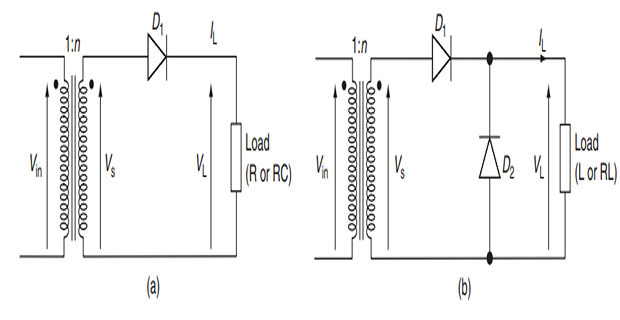
Topology (a) applicable for resistive and/or capacitive loads.
Topology (b) suitable for inductive and/or resistive-inductive loads.
Role of Freewheeling Diode (D2):
Needed to provide path for trapped kinetic energy in inductor to discharge when D1 is reverse-biased.
Allows inductor current to freewheel through it when D1 is OFF.
Transformer Configuration
Mains/grid voltage (\(V_{in}\)) applied at primary of transformer.
Voltage at secondary of transformer is \(nV_{in}\), where \(n\) is turns ratio.
Choice of turns ratio \(n\) depends on load voltage requirements.
Operational Dynamics
When dot poles of transformer are positive, \(D_1\) conducts and load voltage (\(V_L\)) follows secondary voltage (\(V_s\)).
\(D_2\) in topology (b) is reverse-biased and OFF during this time.
When \(V_s\) goes negative with respect to dot pole, \(D_1\) switches OFF.
If load is inductive, inductive current freewheels through \(D_2\).
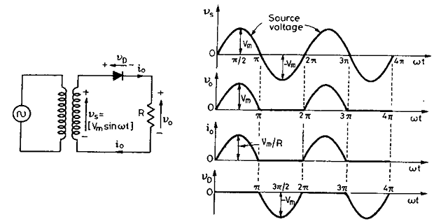
Single-Phase Diode Rectifier with R-Load

Average value of output (or load) voltage
\[\begin{aligned} V_{0} & =\frac1{2\pi}{\left[\int_0^\pi V_m\sin\omega td(\omega t)\right]} \\ &=\frac{V_m}{2\pi}\mid-\cos\omega t\mid_0^\pi=\frac{V_m}\pi \end{aligned}\]RMS value of output voltage
\[\begin{aligned} V_{or}& =\left[\frac1{2\pi}\int_0^\pi V_m^2\sin^2\omega t\cdot d(\omega t)\right]^{1/2} \\ &=\frac{V_m}{\sqrt{2\pi}}\left[\int_0^\pi\frac{1-\cos2\omega t}2\cdot d(\omega t)\right]^{1/2} \\ &=\frac{V_m}2 \end{aligned}\]
Average value of the load current:
\[I_o = \dfrac{V_o}{R} = \dfrac{V_m}{\pi R}\]RMS value of the load current:
\[I_{or} = \dfrac{V_{or}}{R} = \dfrac{V_m}{2R}\]- \[=\dfrac{V_m}{R}\]Peak value of the load (or diode) current:
- \[\mathrm{PIV} = V_m = \sqrt{2} \times \text{RMS value of the TF secondary voltage}\]Peak inverse voltage (PIV) is the maximum voltage that appears across the diode during its blocking state
Power delivered to resistive load:
\[\begin{aligned} &=V_{or} \cdot I_{or}\\ &=V_{or}\cdot I_{or}=\frac{V_{m}}{2}\cdot\frac{V_{m}}{2R}=\frac{V_{m}^{2}}{4R}=\frac{V_{s}^{2}}{2R}=I_{or}^{2} \cdot R \end{aligned}\]Input power factor:
\[\begin{aligned} &=\frac{\text{Power delivered to load}}{\text{Input VA}}\\&=\frac{V_{or}\cdot I_{or}}{V_{s}\cdot I_{or}}=\frac{V_{or}}{V_{s}}=\frac{\sqrt{2}V_{s}}{2V_{s}}=0.707\mathrm{~lag}.\end{aligned}\]