Firing Angle Analysis for Transient Current
Firing Angle to Ensure No Transient Current
Key Formula
The firing angle to ensure no transient current is:
-
Where:
-
\(\omega = 2\pi f\) is the angular frequency (rad/s)
-
\(L\) is the inductance (H)
-
\(R\) is the resistance (\(\Omega\))
-
-
This angle corresponds to the load impedance angle
-
At this firing angle, the transient component becomes zero
Maximum Transient Current Condition
Maximum Transient Condition
For maximum transient current:
-
Where \(\phi = \tan^{-1}\left(\frac{\omega L}{R}\right)\) is the load impedance angle
-
This represents the worst-case scenario for transient current
-
Practical implication: Avoid firing at this angle for smooth operation
Half-Controlled Converters with RL Load and Freewheeling Diode
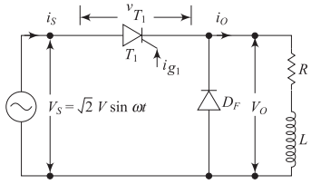
Circuit Configuration
-
Components:
-
Single-phase AC source
-
Thyristor (\(T_1\))
-
RL load (R, L)
-
Freewheeling diode (\(D_f\))
-
-
Purpose of freewheeling diode:
-
Provides path for inductive current
-
Improves converter performance
-
Reduces voltage stress on thyristor
-
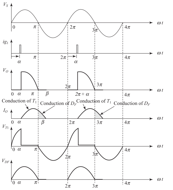
Discontinuous Mode Operation
Discontinuous Mode: Operating Principle
Mode I: Thyristor Conduction (\(\alpha < \omega t < \pi\))
-
Thyristor \(T_1\) is forward biased during positive half-cycle
-
Triggering pulse applied at \(\omega t = \alpha\)
-
Current flows: Source \(\rightarrow\) \(T_1\) \(\rightarrow\) Load
Mode II: Freewheeling Diode Conduction (\(\pi < \omega t < \pi + \beta\))
-
Input polarity reverses at \(\omega t = \pi\)
-
Inductive current continues through \(D_f\)
-
Current flows: \(D_f\) \(\rightarrow\) Load (decaying)
-
Current becomes zero at \(\omega t = \pi + \beta\)
Discontinuous Mode: Performance Analysis
Average Output Voltage
Average Output Current
-
Note: \(V_m = \sqrt{2}V\) is the peak input voltage
-
Output voltage is higher compared to without freewheeling diode
-
Current ripple is reduced due to freewheeling action
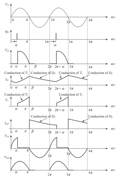
Continuous Mode Operation
Continuous Mode: Mode I Analysis
Mode I: Thyristor \(T_1\) Conduction (\(\alpha < \omega t < \pi\))
Voltage equation:
Output current solution:
-
Where: \(Z = \sqrt{R^2 + (\omega L)^2}\) and \(\phi = \tan^{-1}\left(\frac{\omega L}{R}\right)\)
-
\(I_o\) is the initial current at \(\omega t = \alpha\)
Continuous Mode: Mode II Analysis
Mode II: Freewheeling Diode \(D_f\) Conduction (\(\pi < \omega t < 2\pi + \alpha\))
Voltage equation:
Output current solution:
-
\(I_\pi\) is the current at \(\omega t = \pi\) (end of Mode I)
-
Current decays exponentially with time constant \(\tau = \frac{L}{R}\)
-
Mode II continues until the next firing pulse at \(\omega t = 2\pi + \alpha\)
Advantages of Freewheeling Diode
Performance Improvements
-
Higher output voltage: Better voltage utilization
-
Improved power factor: Reduced reactive power demand
-
Better current waveform: Reduced current ripple
-
Enhanced efficiency: Energy stored in inductance is transferred to load resistance
-
Reduced voltage stress: Lower reverse voltage across thyristor
Key Benefit
The stored magnetic energy in inductance \(L\) is efficiently transferred to the resistive load \(R\) during freewheeling, improving overall converter efficiency.
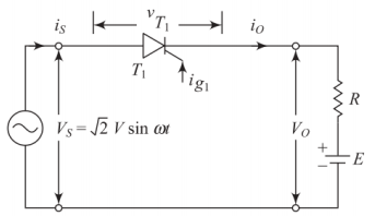
Half-Wave Controlled Converters with RE Load
RE Load Configuration
-
Applications:
-
Battery charging systems
-
DC motor drives
-
Electroplating processes
-
-
Load components:
-
Resistance (R): Internal resistance
-
EMF source (E): Battery voltage
-
-
Operation principle:
-
Thyristor conducts when \(V_s > E\)
-
Current flows only during charging
-
RE Load: Operating Conditions
Conduction Conditions
Thyristor conducts when:
-
Input voltage \(V_s > E\) (forward bias condition)
-
Gate pulse is applied at \(\omega t = \alpha\)
Natural conduction angle:
-
When \(V_s < E\): Thyristor is reverse biased and turns OFF
-
Extinction angle \(\beta_2 = \pi - \beta_1\) (due to symmetry)
-
Condition for conduction: \(\alpha \leq \beta_1\) for natural conduction
RE Load: Current and Power Analysis
Charging Current
During conduction period \(\beta_1 < \omega t < \beta_2\):
Average Charging Current
-
Power delivered to battery: \(P_b = E I_{dc}\)
-
Power loss in resistance: \(P_R = I_{rms}^2 R\)
-
Rectifier efficiency: \(\eta = \frac{P_b}{P_b + P_R}\)
RE Load: Controlled Operation (\(\alpha > \beta_1\))
Modified Operating Range
When firing angle \(\alpha > \beta_1\):
-
Conduction period: \(\alpha < \omega t < \beta_2\)
-
Reduced charging time
-
Lower average charging current
Performance equations
Average charging current:
RMS current:
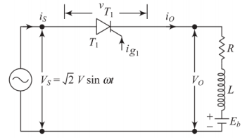
Half-Wave Controlled Converters with RLE Load
RLE Load: Introduction and Applications
Load Components
-
R: Armature resistance / Internal resistance
-
L: Armature inductance / Circuit inductance
-
E: Back EMF / Counter EMF
Primary Applications
-
DC Motor Control: Armature circuit modeling
-
Battery Charging: With series inductance
-
Electrochemical Processes: Industrial applications
Key Characteristic
RLE load makes the most comprehensive load model for practical applications.
RLE Load: Operating Constraints
Minimum Firing Angle
-
Constraint: \(\alpha \geq \delta_0\) for thyristor conduction
-
When \(\alpha < \delta_0\): Input voltage \(< E\), thyristor remains OFF
Operating Range
-
Minimum firing angle: \(\alpha_{min} = \delta_0\)
-
Maximum firing angle: \(\alpha_{max} = \pi - \delta_0\)
-
Practical range: \(\delta_0 \leq \alpha \leq \pi - \delta_0\)
RLE Load: Circuit equation and Solution
Voltage equation
When thyristor conducts (\(\alpha < \omega t < \beta\)):
Complete Current Solution
-
Where: \(Z = \sqrt{R^2 + (\omega L)^2}\) and \(\tan\phi = \frac{\omega L}{R}\)
-
Current has both steady-state and transient components
RLE Load: Performance Parameters
Average Charging Current
Average Output Voltage
-
\(\beta\) is the extinction angle (when current becomes zero)
-
Both voltage and current depend on the conduction angle \((\beta - \alpha)\)
-
Control strategy: Vary \(\alpha\) to control average values
Summary and Key Takeaways
Summary: Key Concepts
Firing Angle Considerations
-
No transient: \(\alpha = \tan^{-1}\left(\frac{\omega L}{R}\right)\)
-
Maximum transient: \(\alpha = 90° + \phi\)
Load Type Characteristics
-
RL Load + Freewheeling Diode: Improved performance, continuous current
-
RE Load: Battery charging, natural conduction constraints
-
RLE Load: DC motor control, combined effects of R, L, and E
Performance Enhancement
-
Freewheeling diode significantly improves converter performance
-
Proper firing angle selection minimizes transients
-
Load characteristics determine operating constraints