Introduction to Controlled Rectifiers
Introduction to Controlled Rectifiers
Limitations of Uncontrolled Converters
-
Average output voltage is constant for given load and fixed input voltage
-
Variable output requires additional components:
-
Auto-transformer
-
VARIAC
-
Tap changing transformer
-
Disadvantages of Traditional Methods
-
Large size and heavy weight
-
High cost and complexity
-
Limited control range
Solution: Phase Controlled Converters
Provide better solutions with compact design and precise control
Applications of Controlled Rectifiers
Industrial Applications
Extensively used in various industrial sectors:
-
Electric traction systems
-
Steel rolling mills
-
Paper mills
-
Textile mills
-
Magnet power supply
-
Electro-mechanical devices
Power Semiconductor Devices
Power Diode Operation
-
ON: Forward biased and input voltage \(>\) cut-off voltage
-
OFF: When reverse biased
SCR Operation
-
ON: Forward biased + triggering pulse applied
-
OFF: Reverse bias or commutation voltage
Key Characteristic
Devices are turned ON and OFF sequentially and repetitively to control power flow
Commutation Methods for SCRs
Natural Commutation
(Line Commutation)
-
SCR turns OFF when applied AC voltage becomes zero
-
Commonly used in controlled rectifier circuits
-
Simple and reliable
Forced Commutation
(Artificial Commutation)
-
Uses specially designed circuit
-
Applies reverse voltage across SCR
-
Forces SCR to turn OFF
Classification of Single-Phase Controlled Rectifiers
Classification Overview
Basic Principle
When diodes are replaced by SCRs in uncontrolled converters:
-
Controllable output voltage obtained by controlling delay angle (\(\alpha\))
-
Variable voltage available at output terminals
Classification Based on Pulses
-
Single-phase half-wave (1-pulse) controlled converter
-
Single-phase full-wave (2-pulse) controlled converter
Detailed Classification
Single-Phase Controlled Converters
-
Half-wave or 1-pulse converters:
-
Without free wheeling diode
-
With free wheeling diode (\(D_F\))
-
-
Full-wave or 2-pulse converters:
-
Without free wheeling diode (\(D_F\)) - full-converter
-
With free wheeling diode (\(D_F\)) - semi-converter
-
Half-Controlled Converters with Resistive Load
Circuit Configuration - R Load
Circuit Components
-
Single-phase AC source
-
Thyristor \(T_1\) (controlled switch)
-
Resistive load (R)
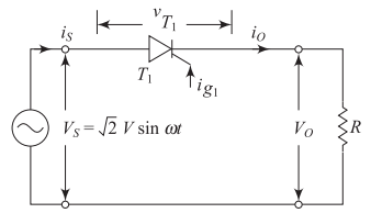
Thyristor Conduction Conditions
Thyristor \(T_1\) conducts only when:
-
Anode is positive with respect to cathode
-
Positive gate pulse is applied
Otherwise operates in forward blocking state
Operating Principle - R Load
Positive Half Cycle
-
Thyristor \(T_1\) is forward biased
-
Fired at \(\omega t = \alpha\)
-
Starts conduction
-
Continues up to \(\omega t = \pi\)
Negative Half Cycle
-
Thyristor \(T_1\) is reverse biased
-
Turns OFF at \(\omega t = \pi\)
-
Natural commutation occurs
-
Load current becomes zero
Control Mechanism
Average output voltage is controlled by varying firing angle \(\alpha\)
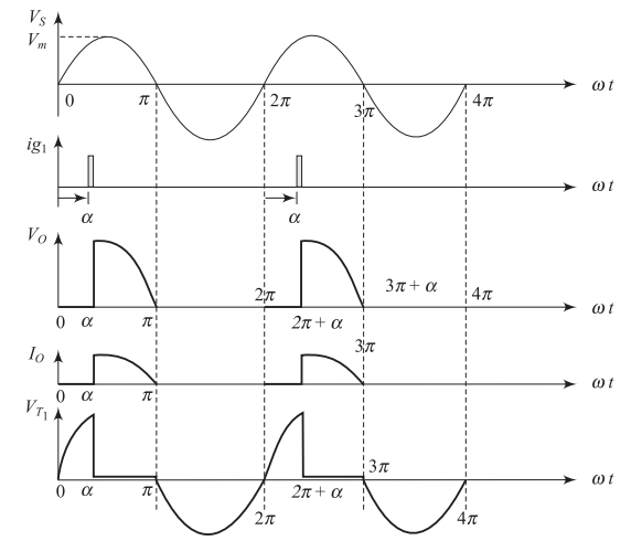
Key Characteristics - R Load
Waveform Properties
-
Output voltage waveform same as output current waveform
-
Zero phase difference in resistive load
-
DC output voltage always positive
-
Current also positive
Operation Quadrant
-
Operates in first quadrant only
-
Known as half-wave semi-converter
Mathematical Analysis - R Load
Output Voltage Expression
Average Output Voltage
-
When \(\alpha = 0\): \(V_{dc} = \frac{2\sqrt{2}V}{\pi}\) (Maximum)
-
When \(\alpha = \pi\): \(V_{dc} = 0\) (Minimum)
Performance Parameters - R Load
Voltage and Current Parameters
RMS Output Voltage:
Average and RMS Current:
Power Analysis - R Load
Power Calculations
DC Output Power:
AC Output Power:
Quality Factors - R Load
Form Factor
Ripple Factor
Transformer Utilization Factor (TUF)
Firing Angle Analysis - R Load
Key Operating Points
Maximum Average Output (50% condition):
-
Maximum average output voltage at \(\alpha = 0°\)
-
For 50% of maximum: \((1 + \cos\alpha) = 1\)
-
Result: \(\alpha = 90°\)
Control Range
DC output voltage varies from \(\frac{2\sqrt{2}V}{\pi}\) to \(0\) when firing angle varies from \(\alpha = 0\) to \(\alpha = \pi\)
Half-Controlled Converters with RL Load
Circuit Configuration - RL Load
Circuit Components
-
AC voltage source
-
Thyristor (controlled switch)
-
Resistive-inductive load (RL)
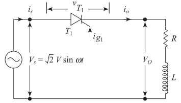
Key Difference
Operation differs significantly from pure resistive load due to inductance effects
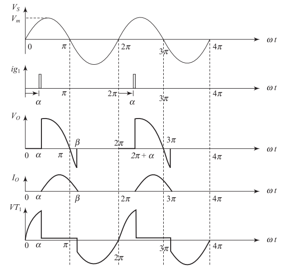
Operating Principles - RL Load
Positive Half-Cycle Operation
-
Thyristor forward biased
-
Gate pulse applied at \(\omega t = \alpha\)
-
Thyristor turns ON
-
Input voltage applied across load
Inductive Load Effects
-
Current increases gradually from zero
-
Reaches maximum, then decreases
-
Current continues to flow even after input voltage reverses
Conduction Characteristics - RL Load
Conduction Period Definition
-
Thyristor starts conduction: \(\omega t = \alpha\) (firing angle)
-
Thyristor turns OFF: \(\omega t = \beta\) (extinction angle)
-
Conduction period: \(\beta - \alpha\) (conduction angle)
Important Note
Thyristor remains ON despite reverse bias due to inductive current continuation
Output Voltage Expression - RL Load
Piecewise Voltage Expression
Two Operating Modes
-
Rectification mode (\(\alpha < \omega t < \pi\)): Power flows from supply to load
-
Inversion mode (\(\pi < \omega t < \beta\)): Power flows from load to supply
Current Analysis - RL Load
Circuit Voltage Equation
When thyristor is ON:
Current Components
Steady-state: \(i_{ss}(t) = \frac{V_m}{Z} \sin(\omega t - \phi)\)
Transient: \(i_{tr}(t) = Ae^{-\frac{R}{L}t}\)
Where: \(Z = \sqrt{R^2 + (\omega L)^2}\) and \(\tan \phi = \frac{\omega L}{R}\)
Complete Current Expression - RL Load
Total Output Current
Boundary Condition
At extinction angle: \(i_o = 0\) when \(\omega t = \beta\)
Voltage Analysis - RL Load
Average Output Voltage
-
Maximum when \(\beta = \pi\)
-
Decreases as \(\beta\) increases
RMS Output Voltage
Form Factor Analysis - RL Load
Form Factor Definition
Simplified Expression
Form factor indicates the shape of the output waveform
Transient Analysis - RL Load
Transient Current Component
Special Cases
-
No transient current: when \(\sin(\alpha - \phi) = 0\)
-
Maximum transient: when \(\sin(\alpha - \phi) = \pm 1\)
These conditions are important for circuit design and protection
Quadrant Operation - RL Load
Two-Quadrant Operation
Single-phase half-wave controlled rectifier with RL load operates in:
-
First quadrant: Rectification mode
-
Fourth quadrant: Inversion mode
Key Features
-
Average output voltage can be positive or negative
-
Depends on firing angle
-
Bidirectional power flow capability
-
Makes it a "full converter"
Summary and Applications
Summary
Single-Phase Half-Wave Controlled Rectifiers
With R Load:
-
Simpler analysis
-
Current follows voltage
-
First quadrant operation
With RL Load:
-
Complex due to inductance
-
Two-quadrant operation
-
Bidirectional power flow
Key Control Parameters
-
Firing angle \(\alpha\) controls output
-
Extinction angle \(\beta\) depends on load characteristics
-
Conduction angle \(\beta - \alpha\) determines power transfer
Applications
Practical Applications
Power Supplies
-
DC power supplies
-
Variable voltage sources
Energy Storage
-
Battery charging
-
Energy recovery systems
Motor Control
-
DC motor control
-
Speed regulation
Advantages
-
Precise voltage control
-
High efficiency
-
Compact design
-
Cost-effective solution