Introduction
Introduction to Single-Phase Controlled Rectifiers
Key Concepts
-
Controlled rectifiers convert AC to DC using thyristors (SCRs)
-
The output voltage can be controlled by varying the firing angle ( \(\alpha\))
-
Thyristors turn OFF when current becomes zero (natural commutation)
-
Conduction angle = \(\beta - \alpha\)
-
Circuit turn OFF time depends on the conduction angle
Applications
DC motor drives, battery chargers, electroplating, welding equipment
Single-Phase Full-Wave Controlled Rectifiers Using Centre Tap Transformer
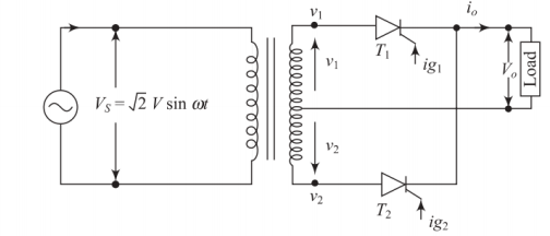
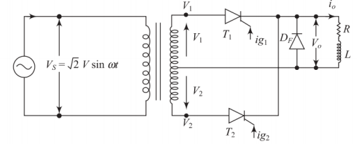
Circuit Configuration
Circuit Features
-
Similar to single-phase full-wave uncontrolled rectifier but with SCRs instead of diodes
-
Uses a center-tap transformer
-
SCR cathodes are commonly connected
-
Single gate drive circuit can turn ON both SCRs
-
SCRs must withstand twice the peak supply voltage (\(2\sqrt{2}V\))
Note
The center-tap configuration provides better transformer utilization compared to bridge configuration
Operation with R Load
Operation with R Load - Positive Half Cycle
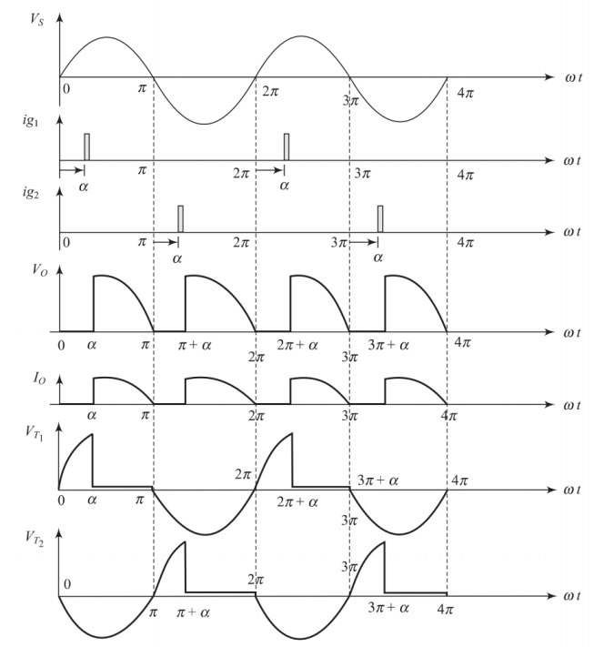
Positive Half Cycle Operation
-
During positive half cycle:
-
Thyristor \(T_1\) is forward biased
-
Thyristor \(T_2\) is reverse biased
-
When gate pulse is applied at \(\omega t = \alpha\), \(T_1\) conducts
-
Current flows through load resistance R and \(T_1\)
-
-
\(T_1\) conducts from \(\omega t = \alpha\) to \(\omega t = \pi\)
Operation with R Load - Negative Half Cycle
Negative Half Cycle Operation
-
During negative half cycle:
-
Thyristor \(T_2\) is forward biased
-
Thyristor \(T_1\) is reverse biased
-
When trigger pulse is applied at \(\omega t = \pi + \alpha\), \(T_2\) conducts
-
Current flows through load resistance R and \(T_2\)
-
-
\(T_2\) conducts from \(\omega t = \pi + \alpha\) to \(\omega t = 2\pi\)
-
Current flows through load in same direction for both half cycles
Analysis for R Load
Voltage and Current Analysis
Average output voltage:
-
When \(\alpha = 0^{\circ}\): \(V_{av} = \frac{2\sqrt{2}V}{\pi}\) (maximum)
-
When \(\alpha = 90^{\circ}\): \(V_{av} = 0\)
-
When \(\alpha = 180^{\circ}\): \(V_{av} = -\frac{2\sqrt{2}V}{\pi}\) (minimum)
Average load current:
Further Analysis for R Load
RMS Values and Power
RMS output voltage:
RMS output current:
Power and Performance Parameters
Power Analysis
DC output power:
AC output power:
Transformer utilisation factor (TUF):
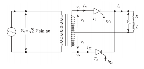
Operation with RL Load
Operation with RL Load
RL Load Characteristics
-
Similar to R load but with inductive load
-
Load current may be continuous or discontinuous depending on inductance value
-
Inductance opposes changes in current, causing current to lag voltage
Current Modes
Discontinuous: Low inductance, current reaches zero
Continuous: High inductance, current never reaches zero
Operation with RL Load - Discontinuous Current
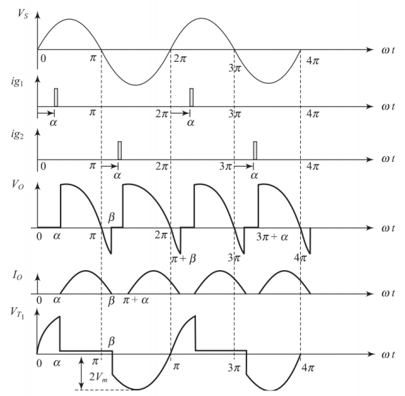
Discontinuous Current Mode
-
When inductance value is low:
-
Load current is discontinuous
-
Each thyristor conducts for less than \(180^{\circ}\)
-
\(T_1\) conducts from \(\omega t = \alpha\) to \(\omega t = \beta\)
-
\(T_2\) conducts from \(\omega t = \pi + \alpha\) to \(\omega t = \pi + \beta\)
-
Average output voltage:
where \(\beta\) is the extinction angle determined by the circuit parameters.
Analysis for RL Load - Discontinuous Current
Current and Voltage Analysis
Average load current:
RMS output voltage:
RMS output current:
Operation with RL Load - Continuous Current
Continuous Current Mode
-
When inductance value is very large:
-
Load current is continuous
-
Each thyristor conducts for \(180^{\circ}\) duration
-
\(T_1\) conducts from \(\omega t = \alpha\) to \(\omega t = \pi + \alpha\)
-
\(T_2\) conducts from \(\omega t = \pi + \alpha\) to \(\omega t = 2\pi + \alpha\)
-
Average output voltage:
Analysis for RL Load - Continuous Current
Voltage Control Range
-
When \(\alpha = 0^{\circ}\): \(V_{av} = \frac{2\sqrt{2}V}{\pi}\) (rectifier mode)
-
When \(\alpha = 90^{\circ}\): \(V_{av} = 0\)
-
When \(\alpha = 180^{\circ}\): \(V_{av} = -\frac{2\sqrt{2}V}{\pi}\) (inverter mode)
DC output voltage range:
RMS output voltage:
Current Expression for Continuous Mode
Output Current Analysis
Output current equation:
Where:
-
\(Z = \sqrt{R^2 + (\omega L)^2}\) is the load impedance
-
\(\phi = \tan^{-1}(\omega L/R)\) is the load phase angle
-
\(A\) is determined by boundary conditions
The constant \(A\) is found using the condition that current at the end of conduction equals the current at the beginning of the next conduction period.
Operation with RL Load and Free Wheeling Diode
Free Wheeling Diode Configuration
Circuit with Free Wheeling Diode
-
Free wheeling diode connected across RL load
-
Also known as half-controlled converter or semi-converter
-
Provides path for inductive current when SCRs are OFF
-
Prevents negative voltage across load
Advantages
-
Improves power factor
-
Reduces ripple in output current
-
Prevents reverse voltage across load
-
Improves converter efficiency
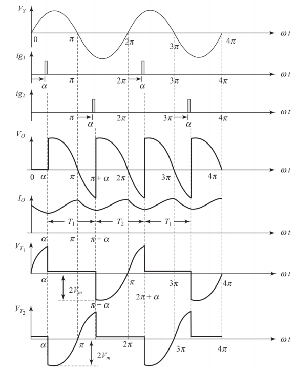
Operation with Free Wheeling Diode
Positive Half Cycle
-
\(T_1\) conducts when triggered at \(\omega t = \alpha\)
-
Current flows through \(T_1\) and load
-
At \(\omega t = \pi\), supply voltage becomes negative
-
\(T_1\) turns OFF, free wheeling diode \(D_F\) conducts
-
Inductive current continues through \(D_F\)
Negative Half Cycle
-
\(T_2\) conducts when triggered at \(\omega t = \pi + \alpha\)
-
Current flows through \(T_2\) and load
-
At \(\omega t = 2\pi\), \(T_2\) turns OFF
-
Free wheeling diode conducts again
Average Values with Free Wheeling Diode
Voltage and Current Analysis
Average output voltage:
Average load current:
-
Output voltage is always positive
-
Better regulation compared to without free wheeling diode
-
Reduced current ripple
RMS Output Voltage Analysis
RMS Output Voltage Calculation
Mathematical Analysis
RMS output voltage:
After integration and simplification:
Where:
-
\(V_s\) is the RMS input voltage per secondary winding
-
\(\alpha\) is the firing angle in radians
Circuit Analysis with Different Load Types
Voltage Equation for RL Circuit
Circuit Differential Equation
Voltage equation:
Valid for \(\alpha < \omega t < \pi + \alpha\) (conduction period)
Where:
-
\(V_s\) is the RMS input voltage
-
\(i_o\) is the instantaneous output current
-
\(L\) is the load inductance
-
\(R\) is the load resistance
Output Current Solution
Current Expression
Complete solution:
Where:
-
\(Z = \sqrt{R^2 + (\omega L)^2}\) is the load impedance
-
\(\phi = \tan^{-1}(\omega L/R)\) is the load phase angle
-
\(A\) is determined by boundary conditions
For continuous conduction: \(i_o(\alpha) = i_o(\pi + \alpha) = I_o\)
Operation with RLE Load
RLE Load Configuration
RLE Load Characteristics
-
Circuit operates similar to half-wave controlled rectifier with RLE load
-
Key difference: load current flows in both half cycles
-
Load current depends on:
-
Firing angle of thyristors (\(\alpha\))
-
Inductive load parameters (\(L\))
-
Ratio of battery voltage to transformer secondary voltage (\(E/V_s\))
-
Applications
Battery charging, DC motor drives with back EMF
Minimum Firing Angle for RLE Load
Critical Firing Angle
Minimum firing angle condition:
Solving for minimum firing angle:
Where:
-
\(E\) is the battery/back EMF voltage
-
\(V_s\) is the RMS secondary voltage per winding
-
For \(\alpha < \alpha_{min}\): No conduction occurs
Summary and Conclusions
Summary
Key Points
-
Single-phase full-wave controlled rectifiers use center-tap transformers with SCRs
-
Output voltage controlled by varying firing angle \(\alpha\) (\(0^{\circ}\) to \(180^{\circ}\))
-
Operation depends on load type:
-
R load: Simple operation, current follows voltage
-
RL load: Current may be continuous or discontinuous
-
RL with FWD: Improved performance, always positive output
-
RLE load: Battery charging applications
-
-
Free wheeling diode improves power factor and reduces ripple
-
Converter can operate in different modes based on firing angle
Performance Comparison
Load Type Comparison
| Load Type | Output Voltage | Current | Power Factor |
|---|---|---|---|
| R Load | \(\frac{2\sqrt{2}V}{\pi}\cos\alpha\) | Discontinuous | Poor |
| RL Load | \(\frac{2\sqrt{2}V}{\pi}\cos\alpha\) | Continuous/Disc. | Poor |
| RL + FWD | \(\frac{\sqrt{2}V}{\pi}(1+\cos\alpha)\) | Improved | Better |
| RLE Load | Variable | Depends on E | Variable |