Introduction to Single-Phase Controlled Rectifiers
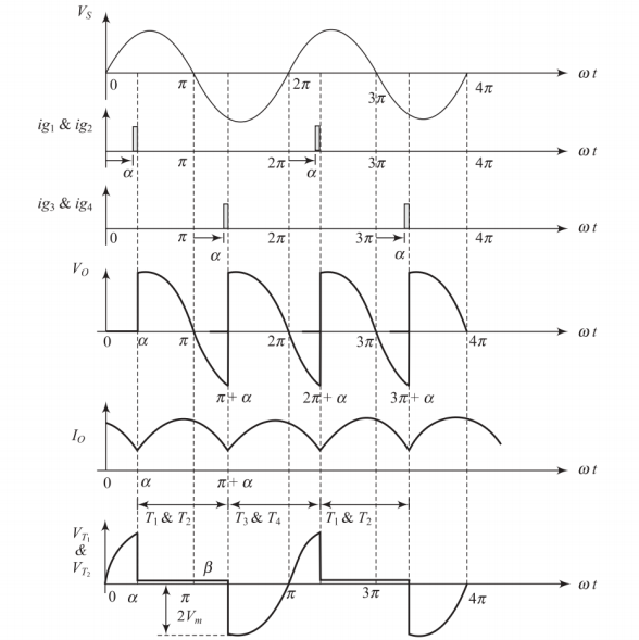
Single-Phase Mid-Point Full Converter
Key Characteristics
-
Average output voltage: \(V_{dc} = \frac{2V_m}{\pi} \cos \alpha\)
-
Average power output: \(P_{av} = V_{dc} \times I_{dc} = \frac{2V_m}{\pi} \cos \alpha \times I_{dc}\)
-
Peak inverse voltage (PIV): Each thyristor withstands \(2V_m\)
-
Maximum power output: 7643.31 W at \(\alpha = 0°\) and \(I_{dc} = 50\) A
Circuit Features
-
Requires center-tap transformer
-
Lower transformer utilization
-
Higher PIV requirements
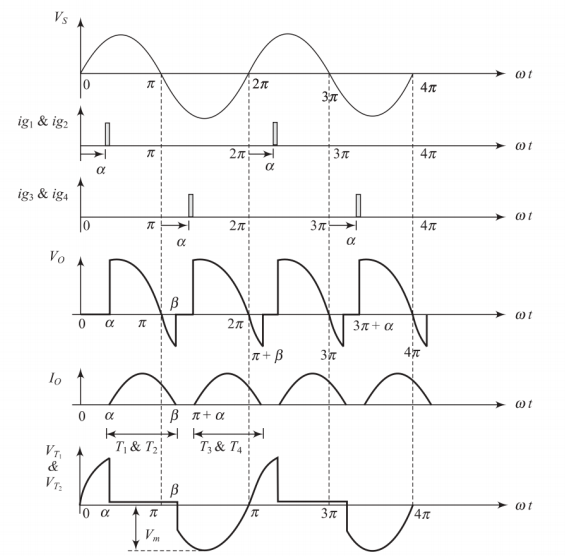
Single-Phase Bridge Converter
Key Characteristics
-
Peak inverse voltage (PIV): Each thyristor withstands \(V_m\)
-
Transformer requirement: No center-tap needed, better transformer utilization
-
Average output voltage: \(V_{dc} = \frac{2V_m}{\pi} \cos \alpha\)
-
Maximum power output: 15286.624 W at \(\alpha = 0°\) and \(I_{dc} = 50\) A
-
Advantage: Same power rating as mid-point converter but with lower PIV requirements
Comparison
Bridge converter can operate at maximum voltage of 480 V compared to mid-point converter’s limitations.
Single-Phase Full-Wave Controlled Bridge Rectifier
Overview and Applications
Industrial Importance
Extensively used in DC motor drives, battery charging, and electrochemical processes
Capabilities
-
Provides unidirectional current
-
Both positive and negative average voltage
-
Four-quadrant operation: rectifier and inverter modes
-
Continuous current capability with inductive loads
Limitations
-
Four SCRs with complex gate drive
-
Higher harmonic content
-
Poor input power factor at large firing angles
-
Complex control circuitry
Classification of Bridge Rectifiers
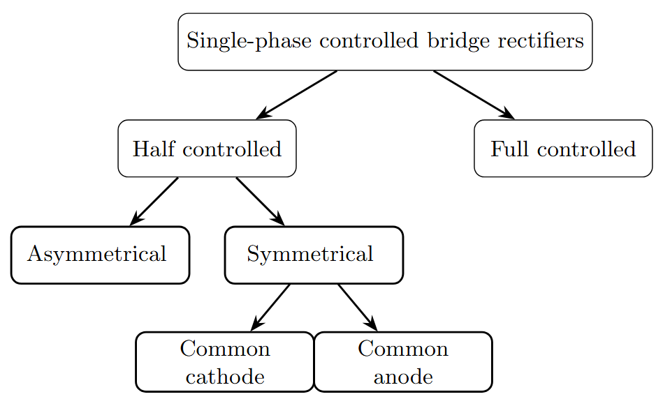
Key Differences
Half Controlled: Two SCRs + Two Diodes (Unidirectional power flow)
Full Controlled: Four SCRs (Bidirectional power flow)
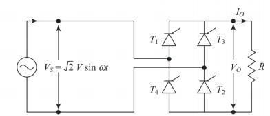
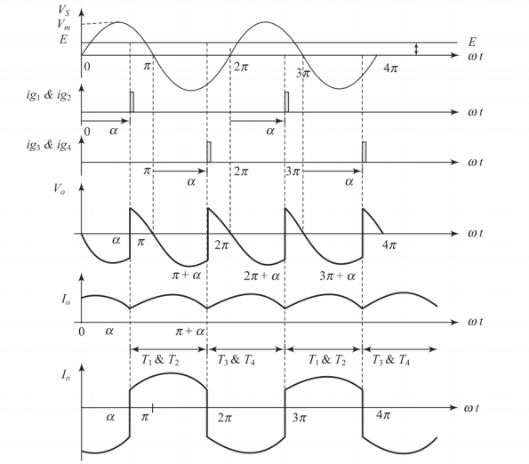
Single-Phase Fully Controlled Bridge Rectifier with R Load
Single-Phase Fully Controlled Bridge Rectifier with R Load
Circuit Features
-
Consists of four thyristors in bridge configuration with resistive load
-
Diagonally paired SCRs (\(T_1\), \(T_2\) and \(T_3\), \(T_4\)) conduct alternately
-
Natural commutation at zero current crossings
-
Conduction angle: \(\pi - \alpha\) for each pair
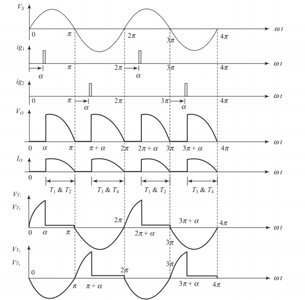
Operating Principle
-
Positive half cycle (\(0 < \omega t < \pi\)): SCRs \(T_1\) and \(T_2\) triggered at \(\omega t = \alpha\)
-
Negative half cycle (\(\pi < \omega t < 2\pi\)): SCRs \(T_3\) and \(T_4\) triggered at \(\omega t = \pi + \alpha\)
-
Load voltage follows input voltage magnitude when SCRs conduct
Performance Analysis - Resistive Load
Key Parameters
-
Average output voltage:
\(V_{dc} = \frac{2\sqrt{2}V}{\pi} \cos \alpha\)
-
Average load current:
\(I_{dc} = \frac{V_{dc}}{R} = \frac{2\sqrt{2}V}{\pi R} \cos \alpha\)
-
RMS output voltage:
\(V_{rms} = V\sqrt{\frac{\pi - \alpha + \frac{1}{2}\sin(2\alpha)}{\pi}}\)
-
Form factor: \(FF = \frac{V_{rms}}{V_{dc}}\), Ripple factor: \(RF = \sqrt{FF^2 - 1}\)
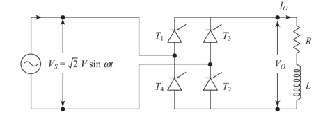
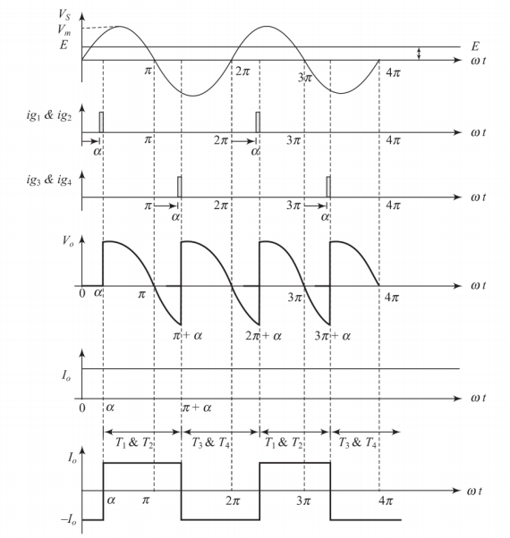
Single-Phase Fully Controlled Bridge Rectifier with RL Load
Single-Phase Fully Controlled Bridge Rectifier with RL Load
Circuit Behavior
-
Inductance causes current to lag voltage
-
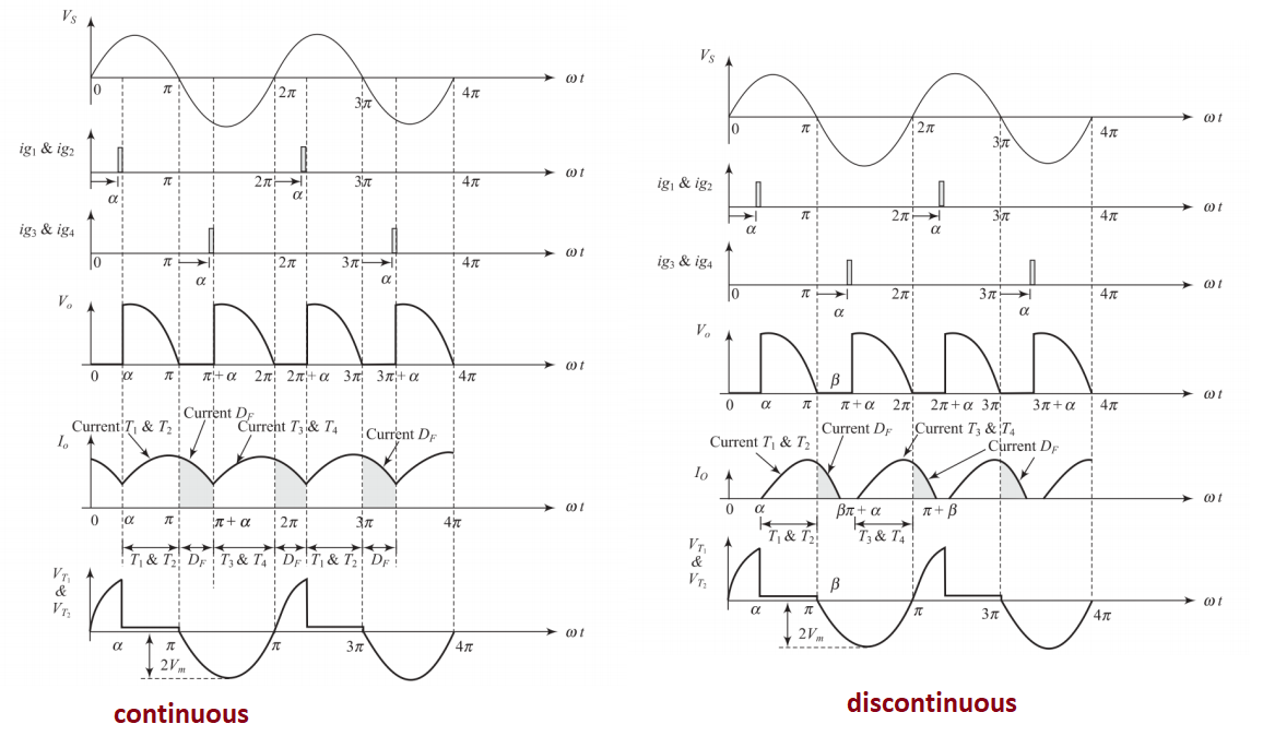
Can operate in continuous or discontinuous conduction mode
-
Boundary depends on \(L\), \(R\), and firing angle \(\alpha\)
-
Critical inductance determines mode transition
Mode Determination
-
Continuous mode: \(L > L_{critical}\) or high load inertia
-
Discontinuous mode: \(L < L_{critical}\) and light loads
-
Time constant \(\tau = \frac{L}{R}\) influences current decay
Continuous Conduction Mode Analysis
Performance Equations - Continuous Current
-
Average output voltage:
\(V_{dc} = \frac{2\sqrt{2}V}{\pi} \cos \alpha\)
-
Average load current:
\(I_{dc} = \frac{V_{dc}}{R} = \frac{2\sqrt{2}V}{\pi R} \cos \alpha\)
-
RMS output voltage:
\(V_{rms} = V\sqrt{\frac{\pi + \alpha}{\pi}}\) (for highly inductive load)
-
Form factor: \(FF = \sqrt{\frac{\pi + \alpha}{\pi}} \times \frac{\pi}{2\cos \alpha}\)
Discontinuous Conduction Mode Analysis
Performance Equations - Discontinuous Current
-
Average output voltage:
\(V_{dc} = \frac{\sqrt{2}V}{\pi} (\cos \alpha - \cos \beta)\)
-
Average load current:
\(I_{dc} = \frac{V_{dc}}{R} = \frac{\sqrt{2}V}{\pi R} (\cos \alpha - \cos \beta)\)
-
RMS output voltage:
\(V_{rms} = V\sqrt{\frac{1}{2\pi}[(\beta - \alpha) + \frac{1}{2}(\sin 2\beta - \sin 2\alpha)]}\)
-
Extinction angle \(\beta\): Determined by \(i(\beta) = 0\) condition
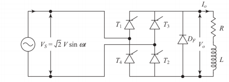
Single-Phase Fully Controlled Bridge Rectifier with Free Wheeling Diode
Single-Phase Fully Controlled Bridge Rectifier with Free Wheeling Diode
Circuit Enhancement
-
Free wheeling diode \(D_f\) connected across the load
-
Conducts when load voltage attempts to reverse
-
Clamps minimum load voltage to zero
-
Prevents inverter mode operation (\(V_{dc} \geq 0\) always)
Advantages
-
Reduces current ripple significantly
-
Improves load current continuity
-
Better transformer utilization factor
-
Reduced harmonic distortion in load current
-
Enhanced system reliability
Performance with Free Wheeling Diode
Modified Performance Equations
-
Average output voltage (\(0 \leq \alpha \leq \pi/2\)):
\(V_{dc} = \frac{\sqrt{2}V}{\pi}(1 + \cos \alpha)\)
-
Average output voltage (\(\pi/2 \leq \alpha \leq \pi\)):
\(V_{dc} = 0\) (Free wheeling diode conducts continuously)
-
Input displacement factor:
\(DF = \cos \alpha\)
-
Power factor improvement: Better than without free wheeling diode
Single-Phase Full-Wave Controlled Bridge Rectifier with RLE Load
Single-Phase Full-Wave Controlled Bridge Rectifier with RLE Load
Primary application
DC motor speed control
R: Armature resistance, L: Armature inductance, E: Back EMF
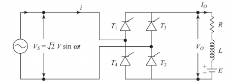
Circuit Equation
\(\sqrt{2}V\sin\omega t = L\frac{di}{dt} + Ri + E\)
where \(\sqrt{2}V\sin\omega t\) is the supply voltage during conduction periods
Operating Conditions
-
SCRs conduct only when \(v_s > E\) (motor back EMF)
-
Minimum firing angle: \(\alpha_{min} = \sin^{-1}\left(\frac{E}{\sqrt{2}V}\right)\)
-
For \(\alpha < \alpha_{min}\): No conduction possible
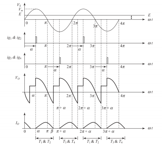
Discontinuous Current Analysis - RLE Load
Current Expression
For \(\alpha \leq \omega t \leq \beta\) (extinction angle):
\(i(t) = \frac{\sqrt{2}V}{Z}[\sin(\omega t - \phi) - \sin(\alpha - \phi)e^{-\frac{R(\omega t - \alpha)}{\omega L}}] - \frac{E}{R}[1 - e^{-\frac{R(\omega t - \alpha)}{\omega L}}]\)
where: \(Z = \sqrt{R^2 + (\omega L)^2}\), \(\phi = \tan^{-1}\left(\frac{\omega L}{R}\right)\)
Key Parameters
-
Average voltage: \(V_{dc} = \frac{\sqrt{2}V}{\pi}[(\cos \alpha - \cos \beta) + \sin\theta(\pi - \beta + \alpha)]\)
-
Average current: \(I_{dc} = \frac{V_{dc} - E}{R}\)
-
Boundary condition: Current extinction when \(i(\beta) = 0\)
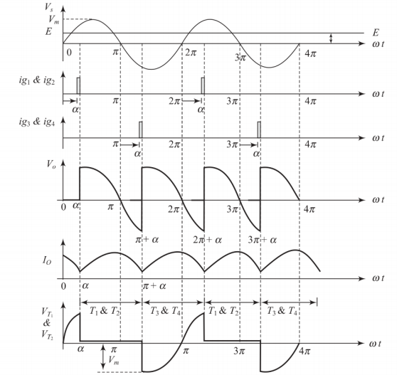
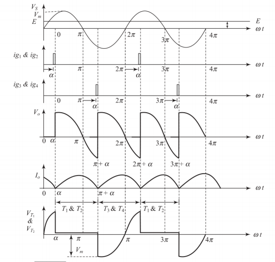
Continuous Current Analysis - RLE Load
Steady-State Operation
-
Periodic boundary condition: \(i(\alpha) = i(\pi + \alpha)\)
-
Average output voltage: \(V_{dc} = \frac{2\sqrt{2}V}{\pi} \cos \alpha\)
-
Average current: \(I_{dc} = \frac{V_{dc} - E}{R}\)
Current Expression
\(i(t) = \frac{\sqrt{2}V}{Z}[\sin(\omega t - \phi) - K] - \frac{E}{\cos\phi}\)
where \(K\) is determined from periodic boundary condition
Motor Operation
-
Motoring mode (\(V_{dc} > E\)): Power delivered to motor
-
Regenerative braking (\(V_{dc} < E\)): Power returned to supply
-
Speed control through firing angle adjustment
Boundary Between Continuous and Discontinuous Conduction
Boundary Conditions
-
Transition occurs when current just touches zero
-
Depends on circuit parameters: \(R\), \(L\), \(E\), and firing angle \(\alpha\)
-
Critical inductance concept applies
Design Considerations
-
Higher inductance favors continuous conduction
-
Lower back EMF increases conduction angle
-
Firing angle affects boundary significantly
-
Load characteristics determine operating mode
Inverter Mode Operation
Four-Quadrant Operation
Rectifier Mode (\(0° \leq \alpha < 90°\))
-
\(V_{dc} > 0\) (positive average voltage)
-
Power flow: AC \(\rightarrow\) DC
-
\(P = V_{dc}I_{dc} > 0\)
-
Forward motoring operation
Inverter Mode (\(90° < \alpha \leq 180°\))
-
\(V_{dc} < 0\) (negative average voltage)
-
Power flow: DC \(\rightarrow\) AC
-
\(P = V_{dc}I_{dc} < 0\)
-
Regenerative braking operation
Key Design Insight
The firing angle \(\alpha\) controls both magnitude and polarity of average output voltage, enabling seamless transition between motoring and regenerative braking.
Harmonic Analysis and Power Quality
Input Current Harmonics
Fourier Series Analysis
For continuous conduction with highly inductive load:
\(i_s(t) = \frac{4I_{dc}}{\pi} \left[\cos\omega t - \frac{1}{5}\cos 5\omega t + \frac{1}{7}\cos 7\omega t - \frac{1}{11}\cos 11\omega t + \cdots\right]\)
Harmonic Components
-
Input current contains only odd harmonics
-
Fundamental component: \(I_1 = \frac{4I_{dc}}{\pi}\)
-
Fifth harmonic: \(I_5 = \frac{4I_{dc}}{5\pi}\)
-
Seventh harmonic: \(I_7 = \frac{4I_{dc}}{7\pi}\)
Power Quality Metrics
Key Performance Indicators
-
Total harmonic distortion (THD):
\(THD = \sqrt{\left(\frac{I_{rms}}{I_1}\right)^2 - 1} = \frac{\sqrt{\pi^2 - 8}}{\sqrt{8}} = 48.34\%\)
-
Displacement power factor: \(DPF = \cos\alpha\)
-
Current distortion factor: \(CDF = \frac{I_1}{I_{rms}} = \frac{2\sqrt{2}}{\pi}\)
-
Input power factor: \(PF = CDF \times DPF = \frac{2\sqrt{2}}{\pi}\cos\alpha = 0.9\cos\alpha\)
Power Calculations
-
Active power: \(P = V \times \frac{2\sqrt{2}I_{dc}}{\pi} \times \cos\alpha\)
-
Reactive power: \(Q = V \times \frac{2\sqrt{2}I_{dc}}{\pi} \times \sin\alpha\)
Comprehensive Performance Summary
| Parameter | R Load | RL Load (Cont.) | RLE Load |
|---|---|---|---|
| Average Voltage | \(\frac{2\sqrt{2}V}{\pi} \cos \alpha\) | \(\frac{2\sqrt{2}V}{\pi} \cos \alpha\) | \(\frac{2\sqrt{2}V}{\pi} \cos \alpha\) |
| Conduction Angle | \(\pi - \alpha\) | \(\pi\) | Variable |
| Power Factor | \(\frac{2\sqrt{2}}{\pi} \cos \alpha\) | \(\frac{2\sqrt{2}}{\pi} \cos \alpha\) | \(\frac{2\sqrt{2}}{\pi} \cos \alpha\) |
| Current Ripple | High | Low | Very Low |
| THD | Variable | 48.34% | 48.34% |
| Applications | Heating | Filtering | Motor Drives |
Design Guidelines
-
Select firing angle based on required output voltage and power flow direction
-
Use free wheeling diode for improved performance (rectifier mode only)
-
Consider harmonic filters for power quality improvement
-
Ensure adequate SCR current and voltage ratings with safety margins
Comparison and Design Considerations
Converter Topology Comparison
| Parameter | Mid-Point | Bridge | Bridge + FWD |
|---|---|---|---|
| Transformer | Center-tap | Normal | Normal |
| PIV Rating | \(2V_m\) | \(V_m\) | \(V_m\) |
| No. of SCRs | 2 | 4 | 4 + 1 Diode |
| Max Power (50A) | 7643.31 W | 15286.6 W | 15286.6 W |
| Inverter Mode | Yes | Yes | No |
| Current Ripple | Medium | Medium | Low |
Selection Criteria
-
Cost vs. Performance: Bridge offers better utilization
-
Power Rating: Higher power applications favor bridge topology
-
Ripple Requirements: Free wheeling diode reduces ripple
-
Bidirectional Power: Full bridge required for inverter operation
Conclusions
Key Takeaways
-
Single-phase controlled bridge rectifiers offer versatile AC-DC conversion
-
Firing angle control enables output voltage regulation and power flow control
-
Load characteristics significantly influence converter performance
-
Four-quadrant operation capability makes them ideal for motor drive applications
-
Trade-offs exist between control flexibility and power quality
Performance Insights
-
Bridge topology offers better transformer utilization than mid-point
-
Free wheeling diode improves current continuity but prevents inverter operation
-
RLE load analysis is crucial for DC motor drive applications
-
Harmonic content increases with firing angle delay