Series-Connected Diodes:
High-voltage applications such as HVDC transmission lines often require diodes with specific voltage ratings.
In such scenarios, a single commercially available diode may not suffice to meet the necessary voltage rating.
To address this limitation, diodes are connected in series to enhance their reverse blocking capabilities.
Two series-connected diodes with reverse bias:
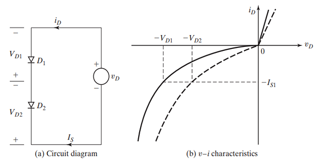
In practice, the \(v-i\) characteristics for the same type of diodes differ due to tolerances in their production process
Under forward-biased conditions, both diodes conduct equal amounts of current, with nearly identical forward voltage drops.
However, in the reverse blocking condition, each diode must handle the same leakage current, potentially leading to significant differences in blocking voltages.
An effective solution to this issue involves ensuring equal voltage sharing among the diodes by connecting a resistor across each diode.
Series-connected diodes with steady-state voltage-sharing characteristic:
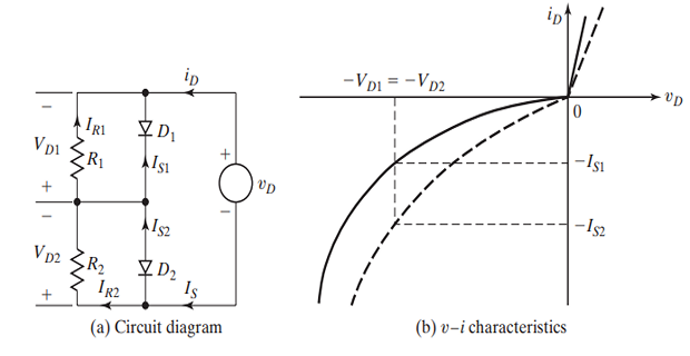
By implementing this approach, the leakage current of each diode would vary, thereby addressing the potential discrepancies in blocking voltages.
- \[\begin{aligned} I_s & = I_{s1} + I_{R1} = I_{s2} + I_{R2}\\ \because \quad I_{R1} & = V_{D1}/R_{1}~\text{and}~I_{R2} = V_{D2}/R_{2} = V_{D1}/R_{2}\\ \Rightarrow~ & I_{s1}+ V_{D1}/R_{1} = I_{s2} + V_{D1}/R_{2}\\ & \text{If~} R_1 = R_2 = R \\ \Rightarrow~ &I_{s1}+ V_{D1}/R = I_{s2} + V_{D2}/R\\ \Rightarrow~ &V_{D1} + V_{D2} = V_s \end{aligned}\]The total leakage current must be shared by a diode and its resistor,
Achieving voltage sharing during transient conditions (such as when switching loads or upon initial application of the input voltage) is facilitated by connecting capacitors across each diode.
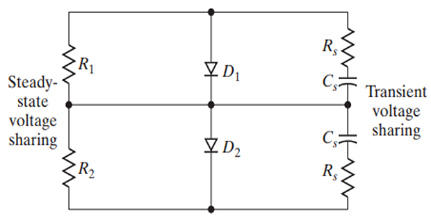
\(R_s\) limits the rate of rise of the blocking voltage.
Problem:
Two diodes are connected in series, to share a total dc reverse voltage of \(V_D = 5~\mathrm{kV}\). The reverse leakage currents of the two diodes are \(I_{s1} = 30~\mathrm{mA}\) and \(I_{s2} = 35~\mathrm{mA}\)
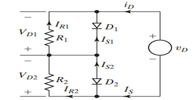
Find the diode voltages if the voltage-sharing resistances are equal \(R_1 = R_2 = R=100~\mathrm{k}\Omega\)
Find the voltage-sharing resistances if the diode voltages are equal \(V_{D1}=V_{D2} = V_D/2\)
Solution:
- \[\begin{aligned} & I_{s1}+ V_{D1}/R= I_{s2} + V_{D2}/R\\ \Rightarrow & I_{s1}+ V_{D1}/R= I_{s2} + (V_{D}-V_{D1})/R\\ \Rightarrow ~&V_{D1}\left( \dfrac{1}{R}+\dfrac{1}{R}\right) =\left( I_{S2}-I_{S1}\right) +\dfrac{V_{D}}{R}\\ \Rightarrow ~&V_{D1}=\dfrac{R}{2}\left( I_{s2}-I_{S1}\right) +\dfrac{V_{D}}{2} \\ & = \dfrac{5~\mathrm{kV}}{2}+ \dfrac{100~k\Omega}{2}(35-30)\times 10^{-3} = 2750~\mathrm{V} \end{aligned}\]Determining the diode voltages:
Determining the diode resistance:
\[\begin{aligned} & I_{S 1}+\frac{V_{D 1}}{R_1}=I_{S 2}+\frac{V_{D 2}}{R_2}\\ \Rightarrow~& R_2=\frac{V_{D 2} R_1}{V_{D 1}-R_1\left(I_{S 2}-I_{S 1}\right)} \end{aligned}\]- \[R_2=\frac{2.5 \mathrm{kV} \times 100 \mathrm{k} \Omega}{2.5 \mathrm{kV}-100 \mathrm{k} \Omega \times\left(35 \times 10^{-3}-30 \times 10^{-3}\right)}=125 \mathrm{k} \Omega\], we get Assuming that
In high-power applications, diodes are often connected in parallel to enhance the current carrying capability, meeting the desired current requirements.
Current distribution among diodes corresponds to their individual forward voltage drops.
To achieve uniform current sharing, equal inductances (such as in the leads) or current-sharing resistors can be provided, although the latter may not be practical due to power losses.
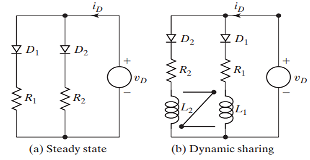
Minimizing discrepancies in current sharing is possible by selecting diodes with similar forward voltage drops or diodes of the same type.
Parallel connection of diodes ensures that the reverse blocking voltages across each diode remain consistent.
Resistors aid in current sharing during steady-state conditions.
Under dynamic conditions, current sharing can be managed by connecting coupled inductors.
When the current through one diode increases, the di/dt across one inductor rises, inducing an opposite-polarity voltage across another inductor.
This induces a low-impedance path through a different diode, effectively shifting the current.
However, the use of inductors may lead to voltage spikes and can be costly and bulky, particularly at high currents.