What is an IGBT?
IGBT = Insulated Gate Bipolar Transistor
-
A hybrid power semiconductor device
-
Combines the best features of:
-
MOSFET: Easy to drive, fast switching
-
BJT: Low voltage drop, high current capability
-
-
Three terminals: Gate (G), Collector (C), Emitter (E)
-
Voltage-controlled device (like MOSFET)
-
Used in medium to high power applications
IGBT = MOSFET input characteristics + BJT output characteristics
Why Do We Need IGBT?
Power Device Limitations:
-
MOSFETs: Good for low voltage only
-
BJTs: Need complex base drive circuits
-
Thyristors: Cannot turn OFF easily
IGBT Solution:
-
High voltage capability (600V - 6.5kV)
-
Simple gate drive (like MOSFET)
-
High current capability (up to kA range)
-
Full control (both ON and OFF)
-
Motor drives
-
UPS systems
-
Welding machines
-
Electric vehicles
-
Solar inverters
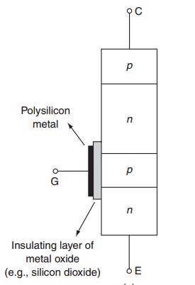
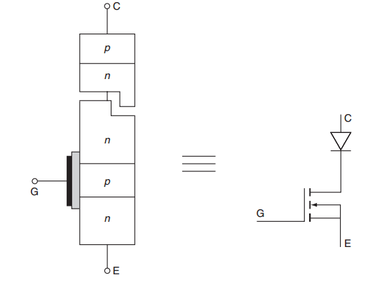
IGBT Structure
Basic Structure:
-
Four-layer semiconductor (P-N-P-N)
-
Gate isolated by thin oxide layer
-
Similar to MOSFET gate structure
-
Vertical power flow design
Key Features:
-
Gate controls electron flow
-
Channel formation under gate
-
Hole injection from collector
-
High current density capability
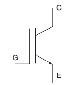
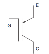
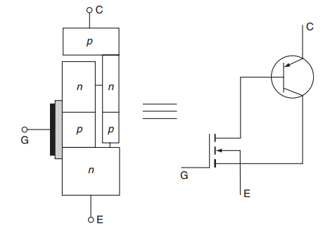
IGBT Symbol and Types
-
Most common type
-
Arrow shows current direction
-
Gate controls the device
-
Less commonly used
-
Reverse current direction
-
Same operating principle
Focus on n-channel IGBTs as they are most widely used.
How IGBT Works - Simple Explanation
Turn-ON Process:
-
Apply positive voltage to gate (V\(_{GE}\) \(>\) V\(_{th}\))
-
Creates electron channel (like MOSFET)
-
Electrons flow from emitter to drift region
-
Holes injected from collector
-
Device turns ON
Turn-OFF Process:
-
Remove gate voltage (V\(_{GE}\) \(<\) V\(_{th}\))
-
Electron channel disappears
-
Stored holes must be removed
-
Device turns OFF
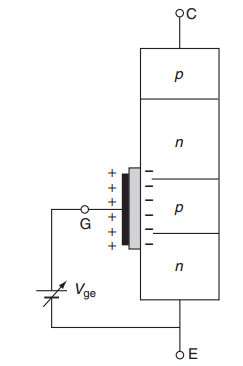
Gate voltage controls electron flow, which controls hole injection
Conductivity Modulation - Why IGBT is Special
When holes from collector enter the drift region, they increase conductivity significantly
Benefits:
-
Low ON-state voltage drop
-
High current handling capability
-
Better than MOSFET for high currents
Trade-off:
-
Slower switching (due to stored charge)
-
Turn-off time longer than MOSFET
Think of it like adding salt to water - increases conductivity!
Lower V\(_{CE(sat)}\) but slower switching
IGBT Equivalent Circuits - Simplified Models
Simple Model:
-
Easy to understand
-
Good for basic analysis
-
Shows unidirectional conduction
Better Model:
-
More accurate for calculations
-
Shows current amplification
-
MOSFET drives BJT base
Use the MOSFET + BJT model for circuit analysis and calculations
Parasitic Thyristor - Important Concept
The Problem:
-
Four-layer structure can form thyristor
-
If activated, causes latch-up
-
Gate loses control
-
Device may be damaged
Prevention:
-
Keep emitter resistance low
-
Proper device layout
-
Stay within Safe Operating Area
-
Use appropriate gate drive
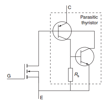
Always mention parasitic thyristor as a limitation of IGBT and its prevention methods
Transfer Characteristics
Key Parameters:
-
Threshold voltage (V\(_{th}\)): 3-6V typically
-
Transconductance (g\(_m\)): Controls current gain
-
Similar to MOSFET transfer curve
Temperature Effects:
-
V\(_{th}\) decreases with temperature
-
Current increases with temperature
-
Important for parallel operation
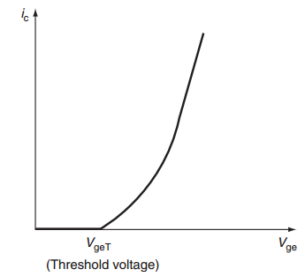
Choose gate voltage 2-3 times higher than V \(_{th}\) for reliable operation
Output Characteristics
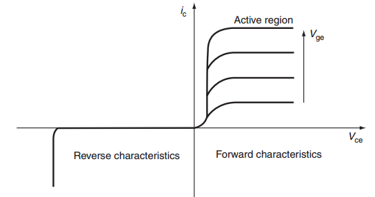
Key Features:
-
Forward blocking capability
-
No reverse blocking (needs antiparallel diode)
-
Saturation region operation
-
V\(_{CE(sat)}\) = 1.5-3V typically
Comparison:
-
Lower V\(_{CE(sat)}\) than MOSFET at high currents
-
Higher V\(_{CE(sat)}\) than BJT
IGBT Switching Behavior
IGBT has tail current during turn-off due to stored minority carriers
Turn-ON:
-
Similar to MOSFET
-
Gate capacitance charging
-
Current rises quickly
-
Voltage falls
Turn-OFF:
-
Gate capacitance discharging
-
Current falls in two stages
-
Tail current - slow decay
-
Limits switching frequency
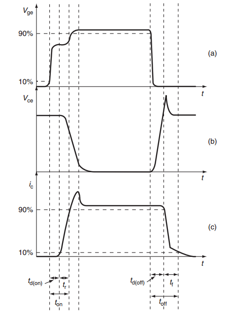
Tail current is the main limitation for high-frequency applications
Gate Drive Requirements
IGBTs need proper gate drive circuits for reliable operation
Voltage Requirements:
-
Turn-ON: +12V to +15V
-
Turn-OFF: -5V to -15V (for fast turn-off)
-
Maximum rating: \(\pm 20~\mathrm{V}\) typically
Current Requirements:
-
Peak current: few amperes
-
Low source impedance preferred
-
Gate resistor for controlling switching speed
Protection:
-
Zener diode across gate-emitter
-
Gate resistor for dv/dt immunity
-
Isolated power supply
V\(_{GE}\) = +15V (ON)
V \(_{GE}\) = -8V (OFF)
R \(_G\) = 10-47\(\Omega\)
IGBT Types - Simplified Classification
Classification based on internal structure and performance
1. Fast IGBTs:
-
Lower switching losses
-
Higher switching frequency (\(>\) 20 kHz)
-
Slightly higher V\(_{CE(sat)}\)
-
Used in: High-frequency converters
Applications:
-
Switch-mode power supplies
-
Motor drives (high speed)
-
Induction heating
2. Low-loss IGBTs:
-
Lower V\(_{CE(sat)}\)
-
Higher conduction efficiency
-
Slower switching
-
Used in: Low-frequency applications
Applications:
-
Traction drives
-
UPS systems
-
Large motor drives
Choose based on switching frequency and power loss requirements
Major Applications
Industrial Applications:
-
Motor drives (most common)
-
Variable frequency drives (VFDs)
-
Uninterruptible Power Supplies (UPS)
-
Welding equipment
-
Induction heating
Power Range:
-
Few kW to MW
-
Voltage: 600V to 6.5kV
-
Frequency: 1 kHz to 100 kHz
Renewable Energy:
-
Solar inverters
-
Wind power converters
-
Energy storage systems
Transportation:
-
Electric vehicle inverters
-
Train traction systems
-
Ship propulsion
Good compromise between switching speed, voltage rating, and drive simplicity
IGBT - Pros and Cons
Advantages:
-
Simple voltage-controlled operation
-
High input impedance (minimal drive power)
-
High current density
-
Good overload capability
-
Wide Safe Operating Area
-
Available in high voltages
-
Cost-effective for medium power
-
Mature and reliable technology
Limitations:
-
Limited switching frequency
-
Tail current causes turn-off delay
-
No reverse conduction
-
Temperature-dependent
-
Latch-up possibility
-
Gate voltage sensitivity
-
Higher voltage drop than MOSFET at low currents
IGBT is excellent for medium-power, medium-frequency applications where simple drive and high power capability are needed
Important Design Considerations
1. Protection Circuits:
-
Gate protection: Zener diode (15V rating)
-
Overcurrent protection: Current sensing + soft turn-off
-
Overvoltage protection: Snubber circuits
2. Thermal Management:
-
Junction temperature \(<\) 150°C
-
Proper heat sink design
-
Thermal interface materials
-
Temperature monitoring
3. Gate Drive Design:
-
Isolated power supply
-
Appropriate gate resistance
-
Short connection paths
-
EMI considerations
Power Device Comparison - Summary Table
| Parameter | IGBT | MOSFET | BJT | Thyristor |
|---|---|---|---|---|
| Drive Power | Low | Low | High | Low |
| Switching Speed | Medium | Fast | Slow | Slow |
| On-state Loss | Medium | High | Low | Low |
| Voltage Rating | High | Medium | High | Very High |
| Current Rating | High | Medium | High | Very High |
| Control | Full | Full | Full | Partial |
| Cost | Medium | Low | Low | Medium |
| Best for | Medium Power | High Freq | Linear Apps | High Power |
Choose IGBT when: Medium power (kW range), moderate frequency (\(<\) 100 kHz), high voltage (\(>\) 600V)
Key Points to Remember
-
IGBT combines MOSFET input + BJT output characteristics
-
Advantages: Easy to drive, high power capability, good SOA
-
Main limitation: Tail current limits switching frequency
-
Applications: Motor drives, UPS, welding, electric vehicles
-
Protection needed: Gate, overcurrent, and overvoltage protection
-
Parasitic thyristor: Must be prevented from latching
-
Best for: Medium power, medium frequency applications
-
Gate drive: +15V ON, -8V OFF, with proper isolation