What is Harmonic Distortion?
-
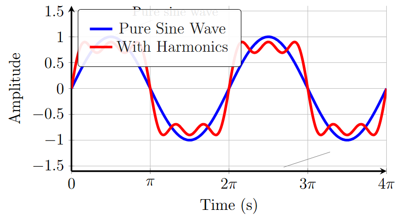
Harmonic distortion refers to the presence of unwanted frequency components (harmonics) in an electrical signal, which deviate from the fundamental frequency.
-
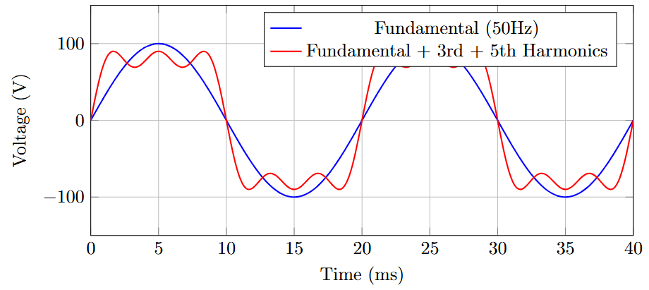
In power electronics, harmonics are typically integer multiples of the fundamental frequency (e.g., 50 Hz or 60 Hz).
-
Caused by non-linear loads and devices, such as rectifiers, inverters, and switched-mode power supplies.
-
Impacts power quality, efficiency, and system performance.
Perfect sinusoidal waveforms contain only the fundamental frequency. Any deviation creates harmonics!
Why Study Harmonic Distortion?
-
Growing Problem: Increasing use of power electronic devices
-
Power Quality: Critical for sensitive equipment
-
Economic Impact: Equipment damage and energy losses
-
Regulatory Compliance: Standards like IEEE 519
-
System Reliability: Prevent resonance and instability
Harmonics in Electrical Systems
-
Fundamental Frequency: The primary frequency of the AC power system (e.g., 50 Hz in Europe, 60 Hz in the USA).
-
Harmonics: Frequencies that are integer multiples of the fundamental (e.g., 2nd harmonic = 100 Hz, 3rd harmonic = 150 Hz for a 50 Hz system).
-
Represented mathematically using Fourier series:
where \(V_n\) is the amplitude and \(\phi_n\) is the phase of the \(n\)-th harmonic.\[v(t) = V_0 + V_1 \sin(\omega t + \phi_1) + V_2 \sin(2\omega t + \phi_2) + V_3 \sin(3\omega t + \phi_3) + \dots\]
Fourier Analysis Visualization
Types of Harmonics
-
Odd Harmonics: 3rd, 5th, 7th, etc. (e.g., 150 Hz, 250 Hz for 50 Hz system). More common in power systems due to symmetrical non-linearities.
-
Even Harmonics: 2nd, 4th, 6th, etc. Less common, often caused by asymmetrical non-linearities.
-
Triplen Harmonics: Multiples of 3 (e.g., 3rd, 9th, 15th). Significant in three-phase systems, especially in neutral conductors.
In balanced 3-phase systems, triplen harmonics are zero-sequence and add up in the neutral conductor!
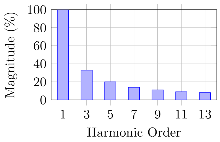
Harmonic Spectrum Analysis
Typical Harmonic Content:
-
6-pulse rectifier: 5th, 7th, 11th, 13th...
-
Square wave: All odd harmonics
-
PWM inverter: Harmonics around switching frequency
Sources of Harmonic Distortion
-
Non-linear Loads:
-
Rectifiers (diode or thyristor-based)
-
Switched-mode power supplies (SMPS)
-
Variable frequency drives (VFDs)
-
Arc furnaces and fluorescent lighting
-
LED drivers and electronic ballasts
-
-
Power Electronic Devices:
-
Inverters and converters introduce harmonics due to switching actions
-
Pulse-width modulation (PWM) techniques
-
Cycloconverters and matrix converters
-
-
Magnetic Saturation: Transformers and inductors operating in saturation regions
Rectifier Circuit Analysis
Single-phase Diode Bridge:
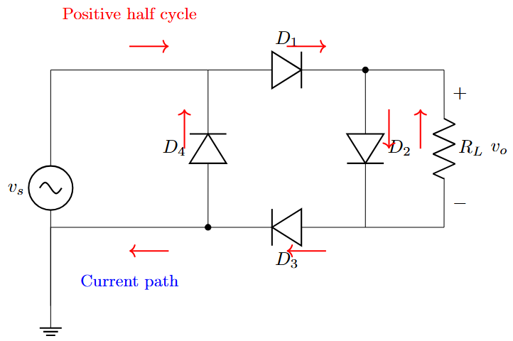
Current Harmonics:
-
Discontinuous current
-
Rich in odd harmonics
-
THD typically 30-80%
Fourier Series:
PWM Inverter Harmonics
PWM Switching Pattern and Harmonics
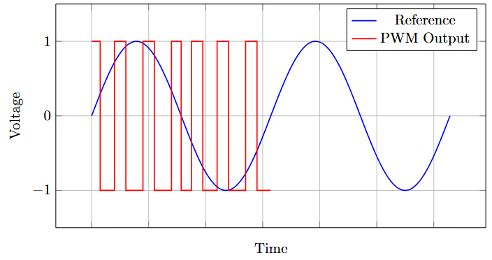
-
Harmonics appear around switching frequency and its multiples
-
Lower order harmonics can be eliminated with proper PWM techniques
-
Trade-off between switching frequency and harmonic content
Impact on Power Systems
-
Equipment Overheating: Harmonics cause additional losses in transformers, motors, and cables
-
Increased copper losses: \(P_{Cu} = I_{rms}^2 R\)
-
Increased core losses in transformers
-
Skin effect in conductors at higher frequencies
-
-
Reduced Efficiency: Increased power losses reduce system efficiency
-
Neutral Overloading: Triplen harmonics accumulate in the neutral conductor of three-phase systems
-
Malfunction of Sensitive Equipment: Harmonics can interfere with control systems and communication devices
-
Power Factor Reduction: Harmonics contribute to reactive power, lowering the power factor
Transformer Derating Due to Harmonics
K-Factor Calculation:
Derating Factor:
Example: For K=13, DF = 0.78
Transformer must be derated to 78% capacity
| Load Type | K-Factor |
|---|---|
| Linear loads | 1.0 |
| Fluorescent lights | 4.0 |
| Computers | 4-10 |
| UPS systems | 13+ |
| VFDs | 5-18 |
Economic and Operational Impacts
-
Increased Maintenance Costs: Due to overheating and premature equipment failure
-
Power Quality Issues: Voltage distortion affects other loads in the system
-
Regulatory Penalties: Non-compliance with standards like IEEE 519 or IEC 61000
-
System Instability: Harmonics can cause resonance in power systems
-
Metering Errors: Harmonics can affect energy measurement accuracy
-
Communication Interference: Harmonics can interfere with power line communication systems
Annual costs due to poor power quality can reach 4-6% of total electrical energy costs!
Quantifying Harmonic Distortion
Total Harmonic Distortion (THD):
Total Demand Distortion (TDD):
Individual Harmonic Distortion (IHD):
Measurement Tools and Techniques
Measurement Equipment:
-
Power quality analyzers
-
Spectrum analyzers
-
Oscilloscopes with FFT capabilities
-
Digital multimeters (True RMS)
-
Harmonic analyzers
Measurement Points:
-
Point of common coupling (PCC)
-
Individual load terminals
-
Transformer secondary
-
Capacitor bank locations
Standards and Limits:
-
IEEE 519: Harmonic limits for power systems
-
IEC 61000-3-2: Equipment harmonic emission limits
-
IEC 61000-3-12: High power equipment limits
IEEE 519 Harmonic Limits
| \(I_{SC}/I_L\) | \(h<11\) | \(11\leq h<17\) | \(17\leq h<23\) | \(23\leq h<35\) | TDD |
|---|---|---|---|---|---|
| \(<20\) | 4.0% | 2.0% | 1.5% | 0.6% | 5.0% |
| \(20-50\) | 7.0% | 3.5% | 2.5% | 1.0% | 8.0% |
| \(50-100\) | 10.0% | 4.5% | 4.0% | 1.5% | 12.0% |
| \(100-1000\) | 12.0% | 5.5% | 5.0% | 2.0% | 15.0% |
| \(>1000\) | 15.0% | 7.0% | 6.0% | 2.5% | 20.0% |
Voltage Distortion Limits:
-
Individual harmonic: 3% (up to 69 kV), 1.5% (>69 kV)
-
THD: 5% (up to 69 kV), 2.5% (>69 kV)
Strategies to Reduce Harmonic Distortion
-
Passive Filters:
-
Tuned LC filters to absorb specific harmonic frequencies
-
Cost-effective but bulky and less flexible
-
Can create resonance issues if not properly designed
-
-
Active Filters:
-
Use power electronics to inject counteracting harmonic currents
-
More effective but expensive
-
Can adapt to changing load conditions
-
-
Hybrid Filters: Combination of passive and active filters
-
Phase-Shifting Transformers: Cancel harmonics in multi-pulse rectifier systems (e.g., 12-pulse or 24-pulse)
Passive Filter Design
Single-Tuned Filter:
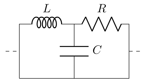
Resonant Frequency:
Quality Factor:

Active Power Filter Operation
Shunt Active Power Filter Principle
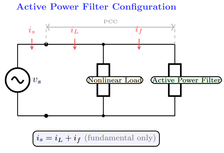
-
APF generates harmonic currents equal and opposite to load harmonics
-
Source current becomes sinusoidal
-
Real-time harmonic detection and compensation
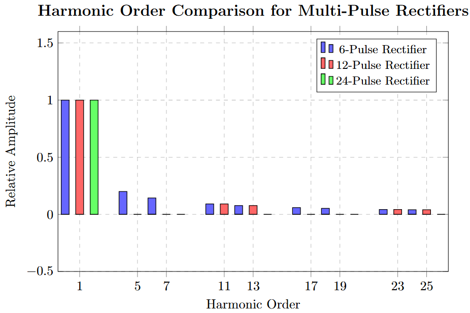
Multi-Pulse Rectifier Systems
12-Pulse Rectifier:
-
Uses phase-shifting transformer
-
Eliminates 5th and 7th harmonics
-
Lowest harmonic: 11th and 13th
-
THD reduced from 30% to 10%
24-Pulse Rectifier:
-
Further harmonic reduction
-
Lowest harmonic: 23rd and 25th
-
THD < 5%
PWM Techniques for Harmonic Reduction
-
Sinusoidal PWM (SPWM):
-
Triangular carrier vs. sinusoidal reference
-
Harmonics appear around switching frequency
-
-
Space Vector PWM (SVPWM):
-
Better DC bus utilization
-
Lower harmonic distortion
-
-
Selective Harmonic Elimination (SHE):
-
Pre-calculated switching angles
-
Eliminates specific low-order harmonics
-
-
Random PWM:
-
Spreads harmonic energy across frequency spectrum
-
Reduces acoustic noise
-
Other Mitigation Approaches
-
Line Reactors: Add inductance to smooth current waveforms
-
Typically 3-5% impedance
-
Reduces current harmonics by 25-50%
-
-
Isolation Transformers: Reduce harmonic propagation
-
K-Rated Transformers: Designed to handle harmonic loads
-
Load Management: Distribute non-linear loads to minimize harmonic impact
-
Power Factor Correction: Properly designed to avoid resonance
-
Compliance with Standards: Design systems to meet IEEE 519 or IEC harmonic limits
Always check for resonance between power factor correction capacitors and system inductance!
Case Study 1: Industrial Plant with VFDs
-
Scenario: Manufacturing facility with 50 variable frequency drives experiencing transformer overheating and premature failures
-
Initial Measurements:
-
THD\(_I\) = 28%, exceeding IEEE 519 limits (8% allowed)
-
Dominant harmonics: 5th (18%), 7th (12%), 11th (8%)
-
Transformer K-factor: 15.2 (originally rated for K=4)
-
Power factor degraded to 0.72
-
-
Solution Implemented:
-
Installed 5th and 7th harmonic tuned passive filters
-
Added 5% line reactors to all VFD inputs
-
Upgraded transformer to K-13 rated unit
-
-
Results:
-
THD\(_I\) reduced to 6.8%
-
Power factor improved to 0.94
-
Transformer temperature reduced by 25°C
-
Annual energy savings: $45,000
-
Case Study 2: Data Center Power Quality Issues
-
Scenario: Large data center with UPS systems and server loads experiencing neutral conductor overheating
-
Problem Analysis:
-
High triplen harmonic content (3rd = 45%, 9th = 15%)
-
Neutral current = 180% of phase current
-
Frequent UPS bypass operations
-
Server equipment malfunctions
-
-
Solution:
-
Installed zigzag transformer for triplen harmonic mitigation
-
Upgraded neutral conductors to 200% of phase conductor size
-
Implemented active harmonic filter at main distribution panel
-
Load balancing across phases
-
-
Outcome:
-
Neutral current reduced to 15% of phase current
-
Improved system reliability and equipment lifespan
-
Compliance with IEEE 519 standards achieved
-
Case Study 3: Hospital Critical Power System
Challenge:
-
Medical equipment sensitive to harmonics
-
LED lighting retrofit created harmonics
-
Imaging equipment interference
-
Emergency power system affected
Measurements:
-
THD\(_V\) = 8.2% (limit: 5%)
-
3rd harmonic = 6.8%
-
5th harmonic = 4.2%
Solutions Applied:
-
Isolation transformers for critical loads
-
Harmonic-mitigating transformers
-
Dedicated circuits for sensitive equipment
-
Power conditioning units
Results:
-
THD\(_V\) < 3%
-
No equipment interference
-
Improved patient safety
Interharmonics and Subharmonics
-
Interharmonics: Frequencies that are non-integer multiples of the fundamental
-
Caused by: Cycloconverters, arc furnaces, wind turbines
-
Can cause flicker and equipment malfunction
-
Measurement challenges due to non-synchronous sampling
-
-
Subharmonics: Frequencies below the fundamental (fractional harmonics)
-
Common in: Static VAR compensators, arc furnaces
-
Can cause subsynchronous resonance in power systems
-
Particularly problematic for rotating machinery
-
Standard harmonic analyzers may not detect interharmonics and subharmonics accurately!
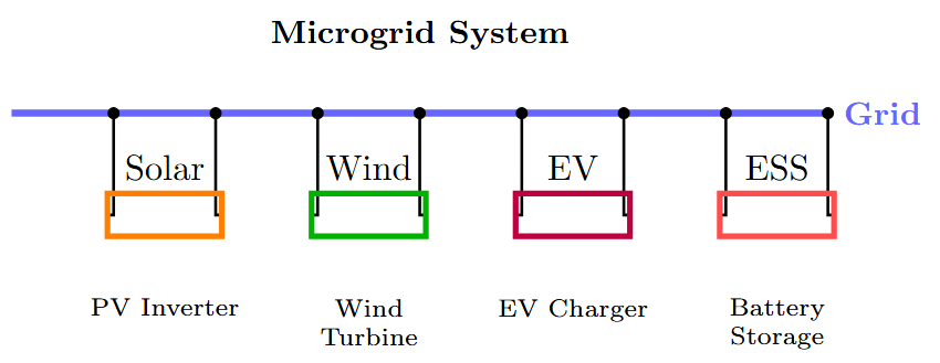
Power Quality in Smart Grids
-
Distributed Generation: Solar inverters, wind turbines introduce new harmonic patterns
-
Electric Vehicle Charging: High harmonic content from EV chargers
-
Energy Storage Systems: Battery inverters contribute to harmonics
-
Smart Grid Technologies:
-
Real-time harmonic monitoring
-
Adaptive filtering systems
-
Coordinated harmonic mitigation
-
Harmonic Resonance Analysis
Series Resonance:
Parallel Resonance:
Resonance Concerns:
-
Amplification of harmonic voltages/currents
-
Equipment overstressing
-
System instability
-
Capacitor failure
Prevention Methods:
-
Frequency scanning studies
-
Detuned filters
-
System impedance analysis
-
Capacitor bank design modifications
Emerging Technologies and Challenges
-
Wide Bandgap Semiconductors:
-
SiC and GaN devices enable higher switching frequencies
-
Potential for reduced filter requirements
-
New EMI challenges at higher frequencies
-
-
Artificial Intelligence in Power Quality:
-
AI-based harmonic prediction and mitigation
-
Machine learning for optimal filter design
-
Predictive maintenance based on harmonic analysis
-
-
Grid-Scale Energy Storage:
-
Large-scale battery systems and harmonics
-
Grid-forming vs. grid-following inverters
-
Harmonic coordination in microgrids
-
Standards Evolution
-
Updated IEEE 519 (2022):
-
New measurement techniques
-
Revised limits for modern loads
-
Improved guidance for distributed resources
-
-
IEC 61000 Series Updates:
-
Enhanced testing procedures
-
New equipment categories
-
Interharmonic and supraharmonic considerations
-
-
Future Considerations:
-
High-frequency harmonics (2-150 kHz)
-
Dynamic harmonic limits
-
Probabilistic harmonic assessment
-
Key Takeaways
-
Understanding: Harmonic distortion is inevitable with non-linear loads but can be managed effectively
-
Measurement: Proper assessment using THD, TDD, and individual harmonic analysis is crucial
-
Standards Compliance: IEEE 519 and IEC 61000 provide essential guidelines for acceptable limits
-
Mitigation Strategy: Choose appropriate solution based on cost, effectiveness, and system requirements
-
System Design: Consider harmonics from the initial design phase to avoid costly retrofits
-
Future Readiness: Stay updated with emerging technologies and evolving standards
Summary
-
Harmonic distortion is a critical issue in modern power electronics systems, caused primarily by non-linear loads and switching devices
-
Effects range from equipment overheating and reduced efficiency to regulatory non-compliance and system instability
-
Comprehensive measurement using standardized metrics (THD, TDD, IHD) is essential for proper assessment
-
Multiple mitigation strategies are available, from passive filters to advanced active solutions and optimized PWM techniques
-
Understanding and managing harmonics is crucial for reliable, efficient, and compliant power systems
-
Future developments in wide bandgap semiconductors, AI, and smart grids will continue to evolve harmonic management strategies
Practical Design Guidelines
-
Always perform harmonic analysis before installing power factor correction capacitors
-
Use K-rated transformers for loads with significant harmonic content
-
Consider line reactors as a cost-effective first step for VFD installations
-
Plan neutral conductor sizing carefully in systems with triplen harmonics
-
Implement harmonic monitoring at critical points in the system
Remember: Prevention is always more cost-effective than remediation!
References and Further Reading
-
IEEE Std 519-2022: IEEE Standard for Harmonic Control in Electric Power Systems
-
IEC 61000-3-2: Electromagnetic compatibility - Limits for harmonic current emissions
-
Dugan, R.C., et al., "Electrical Power Systems Quality," 3rd Edition, McGraw-Hill
-
Arrillaga, J., "Power System Harmonics," 2nd Edition, John Wiley & Sons
-
Rashid, M.H., "Power Electronics Handbook," 4th Edition, Butterworth-Heinemann
-
IEEE Power & Energy Society: Power Quality Application Guide
-
CIGRE Working Group Reports on Power Quality and Harmonics
Online Resources:
-
IEEE Power & Energy Society
-
International Conference on Harmonics and Quality of Power (ICHQP)
-
Power Quality World Magazine