Half-Wave Rectifier With Capacitor Filter
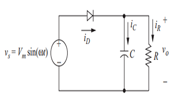
The half-wave rectifier has a parallel \(RC\) load.
\(C\) reduces output voltage (\(v_o\)) variation, making it more like dc.
\(R\) represent an external load, and \(C\) as a filter being the part of the rectifier circuit.
Assume \(C\) is initially uncharged.
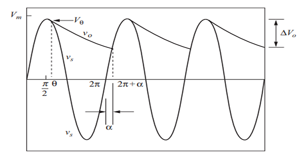
At \(\omega t = 0~\Rightarrow\) \(v_s\) +ve \(\Rightarrow\) diode on (F.B.) \(\Rightarrow\) \(v_o=v_s~\Rightarrow~C\) charges
At \(\omega t = \pi/2~\Rightarrow\) \(v_s=V_m~\Rightarrow~C\) charges to \(V_m\)
After \(\omega t = \pi/2~\Rightarrow~v_s\) decreases \(\Rightarrow~C\) discharge to \(R\)
At some \(\theta~\Rightarrow~v_s<v_o~\Rightarrow\) Diode off R.B. \(\Rightarrow\) Load disconnected from source
\(v_o\) is decaying exponential with \(\tau = RC\) while the diode is off
The diode turns off when the rate at which the \(v_s\) decreases surpasses the rate allowed by the \(\tau_{RC}\).
This point is identified by comparing the rate of change of the \(v_s\) to that of the \(v_c\).
- The output voltage:\[\begin{aligned} v_o(\omega t) &=\begin{cases}V_m\sin\omega t&\quad\text{diode on}\\V_0e^{-(\omega t-\theta)/\omega RC}&\quad\text{diode off}\end{cases}\\ \text{where}~V_\theta & = V_m \sin\theta \end{aligned}\]
- The slopes of these functions:\[\begin{aligned} &\frac{d}{d(\omega t)}[V_m\sin{(\omega t)}]=V_m\cos{(\omega t)} \\ & \frac{d}{d(\omega t)}\Big(V_m\sin\theta e^{-(\omega t-\theta)/\omega RC}\Big)=V_m\sin\theta\Big(-\frac{1}{\omega RC}\Big)e^{-(\omega t-\theta)/\omega RC} \end{aligned}\]
- , the slopes are equal At\[\begin{aligned} V_{m}\cos\theta & =\left(\frac{V_{m}\sin\theta}{-\omega RC}\right)e^{-(\theta-\theta)/\omega RC}=\frac{V_{m}\sin\theta}{-\omega RC}\\ \frac{V_{m}\cos\theta}{V_{m}\sin\theta}&=\frac{1}{-\omega RC}\\ \frac{1}{\tan\theta}&=\frac{1}{-\omega RC} \end{aligned}\]
- and expressing it in proper quadrant Solving for\[\boxed{\theta=\tan^{-1}(-\omega RC)=-\tan^{-1}(\omega RC)+\pi}\]
- is large In practical circuits where\[\boxed{ \theta\approx\frac{\pi}{2} \quad \text{and} \quad V_m\sin\theta\approx V_m }\]
At \(\omega t = 2\pi + \alpha\), the diode turns on in the second period, when \(v_s\) reaches the same value as the decaying exponential output
\[\begin{aligned} &V_m\sin{(2\pi+\alpha)}=(V_m\sin{\theta})e^{-(2\pi+\alpha-\theta)/\omega RC}\\ \Rightarrow &\sin\alpha-(\sin\theta)e^{-(2\pi+\alpha-\theta)/\omega RC}=0\\ & \text{Solved numerically for} ~\alpha \end{aligned}\]
The currents:
\[\begin{aligned} i_R & = \nu_o/R\\ i_C(t) & =C\frac{d\nu_o(t)}{dt}\\ \text{or}~ i_C(\omega t) &=\omega C\frac{d\nu_o(\omega t)}{d(\omega t)} \end{aligned}\]\[\boxed{i_C(\omega t)=\begin{cases}-\left(\dfrac{V_m\sin\theta}{R}\right)e^{-(\omega t-\theta)/\omega RC} ~ \text{for} ~\theta\leq\omega t\leq2\pi+\alpha\\ \text{(diode off)}\\\\\omega CV_m\cos{(\omega t)}~ \text{for}~2\pi+\alpha\leq\omega t\leq2\pi+\theta\\ \text{(diode on)}\end{cases}}\]
- The source current:\[i_S=i_D=i_R+i_C\]
The average \(i_C=0\), so the average \(i_D = i_S\)
- occurs at Peak\[I_{C,\mathrm{peak}}=\omega CV_m\cos(2\pi+\alpha)=\omega CV_m\cos\alpha\]
- \(\omega t = (2\pi+\alpha)\)\(i_R\)\[i_R(2\omega t+\alpha)=\frac{V_m\sin(2\omega t+\alpha)}{R}=\frac{V_m\sin\alpha}{R}\]
- Peak\[I_{D,\mathrm{~peak}}=\omega CV_{m}\cos\alpha+\frac{V_{m}\sin\alpha}{R}=V_{m}\biggl(\omega C\cos\alpha+\frac{\sin\alpha}{R}\biggr)\]
The effectiveness of the capacitor filter is gauged by the variation in the output voltage.
This variation is represented by the difference between the maximum and minimum output voltages, known as the peak-to-peak ripple voltage.
Maximum output voltage is \(V_m\) and minimum voltage occurs at \(\omega t = 2\pi+\alpha\), which is \(V_m \sin\alpha\)
- The peak-to-peak ripple\[\boxed{\Delta V_o=V_m-V_m\sin\alpha=V_m(1-\sin\alpha)}\]
- Approximately, the peak-peak ripple voltage\[\boxed{\Delta V_o\approx V_m\biggl(\frac{2\pi}{\omega RC}\biggr)=\frac{V_m}{fRC}}\]
\(C~\uparrow~\Rightarrow~\Delta V_o~\downarrow~\Rightarrow\) diode conduction interval \(\downarrow~\Rightarrow\) peak \(i_D~\uparrow\)