Introduction to Freewheeling Diodes
A freewheeling diode (also known as a flyback diode, commutating diode, or catch diode) is a crucial component used in circuits with inductive loads to prevent voltage spikes and provide a path for the current to flow when the main switch is opened.
Key Purpose: To protect switching devices and provide continuity for inductive load current, preventing dangerous voltage spikes that could damage circuit components.Fundamental Principle
When current through an inductor is suddenly interrupted, the inductor generates a back EMF given by:
For a rapid change in current (\(\frac{di}{dt}\) is large and negative), this can produce extremely high voltages that can damage semiconductor devices. The freewheeling diode provides an alternate path for this current.
Diode Selection Criteria
- Current Rating: Must handle the peak load current
- Voltage Rating: Should withstand the supply voltage plus safety margin
- Recovery Time: Fast recovery diodes preferred for high-frequency applications
- Forward Voltage Drop: Lower \(V_f\) reduces power losses
Freewheeling Diodes with Switched RL Load
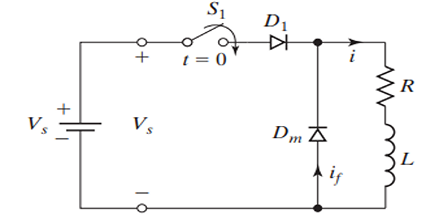
Circuit Operation Principles
- When switch \(S_1\) is closed for time \(t_1\), current flows through the inductive load
- Upon opening \(S_1\), a path must be provided for the current in the inductive load to prevent high voltage induction
- Diode \(D_f\) (freewheeling diode) facilitates a path for the inductive load current to avoid voltage spikes
- Diode \(D_1\) is in series with the switch to prevent negative current flow in the presence of AC input
- In DC supply scenarios, \(D_1\) is unnecessary
- \(S_1\) in conjunction with \(D_1\) mimics the behavior of an electronic switch
Current Behavior Analysis
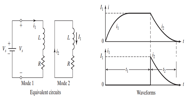
- At \(t = 0^+\), the switch is closed, and the current is zero
- In the absence of \(L\), the current would rise instantaneously
- Due to \(L\), current rises exponentially with an initial slope of \(V_s/L\)
- \(i_1\) and \(i_2\) are the instantaneous currents for Mode 1 and Mode 2
- \(t_1\) and \(t_2\) represent the durations of these modes
Operating Modes
Mode 1: Switch Closed
Begins when the switch is closed at \(t = 0\)
Applying KVL: \(V_s = L\frac{di}{dt} + Ri\)
Solution:
At \(t = t_1\):
- If \(t_1\) is sufficiently long (\(t_1 \gg \frac{L}{R}\)), \(i_1\) reaches steady-state
- Steady-state current: \(I_s = \frac{V_s}{R}\)
- Time constant: \(\tau = \frac{L}{R}\)
Mode 2: Switch Opened
Switch is opened, allowing load current to flow through \(D_f\)
KVL equation (assuming ideal diode):
Solution with initial condition \(i_2(0) = I_1\):
- Current starts to decay exponentially towards zero
- Complete decay occurs if \(t_2 \gg \frac{L}{R}\)
- Energy stored in inductor is dissipated in resistance
Energy Analysis
Energy stored in inductor at switch opening:
This energy is dissipated in the resistance during Mode 2:
This confirms energy conservation in the circuit.
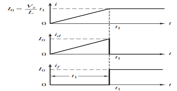
Solved Problem
Given: \(V_s = 220\) V, \(R = 0\), and \(L = 220\) μH
Tasks:
- Draw the load current waveform if the switch is closed for \(t_1 = 100\) μs and then opened
- Determine the final energy stored in the load inductor
Solution:
For \(R = 0\), the circuit equation becomes:
Integrating:
At \(t = t_1\):
Energy stored in inductor:
Note: Since \(R = 0\), when the switch opens, the current continues to circulate through the freewheeling diode indefinitely (in ideal case), maintaining the stored energy.

Single-Phase Diode Rectifier with RL-Load & Freewheeling Diode
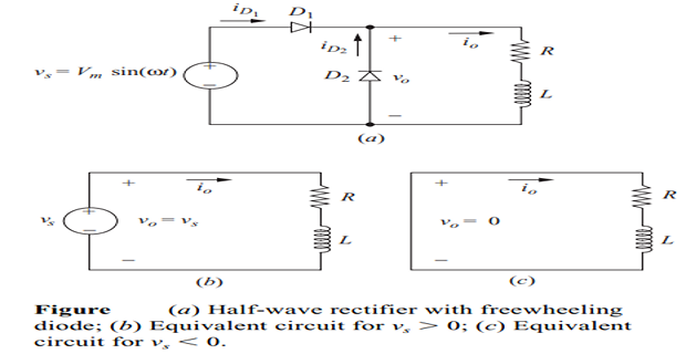
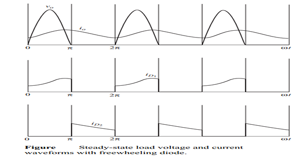
Circuit Analysis
Input voltage: \(v_s(t) = V_m \sin(\omega t)\)
Conduction Analysis:
- Main diode \(D\) conducts when \(v_s > 0\) and current tends to flow
- Freewheeling diode \(D_f\) conducts when main diode turns off
- Load voltage is clamped at zero by the freewheeling diode
Current Equations:
During main diode conduction (\(0 < \omega t < \pi\)):
During freewheeling (\(\pi < \omega t < 2\pi\)):
Effects of Using Freewheeling Diode:
- Voltage Protection: Prevents the load voltage from becoming negative, maintaining \(v_L \geq 0\)
- Energy Recovery: As the energy stored in \(L\) transfers to \(R\) through the freewheeling diode, system efficiency is improved
- Current Smoothing: The load current becomes smoother, reducing ripple content
- Reduced EMI: Eliminates sharp voltage transitions that cause electromagnetic interference
- Improved Power Factor: Better utilization of input current
Performance Metrics
Average Output Voltage:
RMS Output Voltage:
Form Factor:
Ripple Factor:
Single-Phase Diode Rectifier with RLE-Load
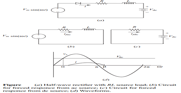
Circuit Analysis
- The diode remains off as long as the AC source voltage is less than the DC voltage
- Diode conduction angle is determined by:
\[V_m\sin(\alpha) = V_{dc}\]\[\alpha = \sin^{-1}\left(\frac{V_{dc}}{V_m}\right)\]
- KVL equation during conduction:
\[V_m\sin(\omega t) = Ri(t) + L\frac{di(t)}{dt} + V_{dc}\]
Impedance and Phase Angle
Load impedance: \(Z = \sqrt{R^2 + (\omega L)^2}\)
Phase angle: \(\theta = \tan^{-1}\left(\frac{\omega L}{R}\right)\)
Time constant: \(\tau = \frac{L}{R}\)
Current Response Analysis
The total current response consists of forced and natural components:
Forced Response:
Natural Response:
Complete current response:
The constant \(A\) is determined by boundary conditions:
Extinction Angle Calculation
The extinction angle \(\beta\) is found by setting \(i(\beta) = 0\):
This transcendental equation typically requires numerical methods for solution.
Power Analysis
-
Average power absorbed by resistor: \(P_R = I_{rms}^2R\)
\[I_{rms} = \sqrt{\frac{1}{2\pi}\int_\alpha^\beta i^2(\omega t)d(\omega t)}\]
-
Average power absorbed by DC source: \(P_{dc} = I_0V_{dc}\)
\[I_0 = \frac{1}{2\pi}\int_\alpha^\beta i(\omega t)d(\omega t)\]
-
Power supplied by AC source (assuming ideal diode and inductor):
\[P_{ac} = I_{rms}^2R + I_0V_{dc}\]\[= \frac{1}{2\pi}\int_0^{2\pi} v(\omega t)i(\omega t)d(\omega t)\]\[= \frac{1}{2\pi}\int_\alpha^\beta (V_m\sin(\omega t))i(\omega t)d(\omega t)\]
Conduction Angle Analysis
Conduction angle: \(\gamma = \beta - \alpha\)
For different values of \(\frac{V_{dc}}{V_m}\):
- If \(\frac{V_{dc}}{V_m} = 0\): \(\alpha = 0°\), maximum conduction
- If \(\frac{V_{dc}}{V_m} = 1\): \(\alpha = 90°\), critical case
- If \(\frac{V_{dc}}{V_m} > 1\): No conduction possible
Practical Applications of Freewheeling Diodes
Motor Drives
- DC Motor Control: Protection during PWM switching in chopper circuits
- Stepper Motors: Preventing back-EMF damage in step sequence changes
- Servo Motors: Smooth operation during direction reversals
Power Supplies
- Switching Power Supplies: Energy recovery in flyback and forward converters
- Buck Converters: Continuous current path during switch-off period
- Boost Converters: Current commutation path
Relay and Solenoid Circuits
- Relay Coils: Protection against contact welding due to arcing
- Solenoid Valves: Extending valve life by reducing switching stress
- Electromagnetic Brakes: Controlled energy dissipation
Inverter and UPS Systems
- PWM Inverters: Protection during dead-time intervals
- UPS Systems: Battery charging circuit protection
- Grid-tie Inverters: Safe operation during grid disconnection
Design Considerations and Limitations
Diode Selection Parameters
- Peak Inverse Voltage (PIV): Must exceed maximum reverse voltage
- Forward Current Rating: Should handle maximum load current with derating
- Reverse Recovery Time (\(t_{rr}\)): Critical for high-frequency applications
- Junction Temperature: Thermal management considerations
Power Losses
Conduction Losses:
Switching Losses:
Limitations
- Forward Voltage Drop: Causes power loss and reduces efficiency
- Reverse Recovery: Can cause switching losses and EMI
- Temperature Dependence: Parameters vary with junction temperature
- Parasitic Elements: Package inductance and capacitance effects
Summary and Key Takeaways
- Protection: Freewheeling diodes protect circuits from voltage spikes caused by inductive loads, preventing damage from \(v_L = -L\frac{di}{dt}\)
- Energy Recovery: They allow stored magnetic energy \(W_L = \frac{1}{2}LI^2\) to be dissipated safely in the circuit
- Improved Performance: Result in smoother current waveforms and better system efficiency
- Essential Component: Critical in power electronic circuits with inductive loads like motors, transformers, and inductors
- Applications: Widely used in rectifiers, choppers, inverters, and switching power supplies
- Design Criteria: Proper selection based on current rating, voltage rating, and recovery characteristics is essential
- Circuit Analysis: Understanding both steady-state and transient behavior is crucial for optimal design
- Power Quality: Reduces harmonics, EMI, and improves overall power factor in rectifier circuits