One Quadrant Converters
Characteristics:
-
Output voltage (\(V_o\)) and output current (\(I_o\)) maintain the same polarity throughout the entire firing angle control range
-
Also known as first quadrant converters
-
Unidirectional power flow: from AC source to DC load
Example: Semi-Converters
-
Both \(V_o\) and \(I_o\) are positive
-
Operate exclusively in rectifier mode
-
Power flows from AC source to DC load
Two Quadrant Converters
Operating Modes:
Rectifier Mode
-
\(V_o\) and \(I_o\) have same polarity
-
Firing angle: \(0 \leq \alpha \leq \frac{\pi}{2}\)
-
First quadrant operation
-
Power: AC source \(\rightarrow\) DC load
Inverter Mode
-
\(V_o\) and \(I_o\) have opposite polarity
-
Firing angle: \(\frac{\pi}{2} \leq \alpha \leq \pi\)
-
Fourth quadrant operation
-
Power: DC load \(\rightarrow\) AC source
Enables bidirectional power flow with unidirectional current
Full Converters - Two Quadrant Operation
Properties:
-
Operate in I-quadrant and IV-quadrant
-
Current direction fixed (unidirectional thyristors)
-
Voltage polarity reversible
First Quadrant
-
\(V_o > 0\), \(I_o > 0\)
-
\(0 \leq \alpha \leq \frac{\pi}{2}\)
-
Controlled rectifier
-
Power: AC \(\rightarrow\) DC
Fourth Quadrant
-
\(V_o < 0\), \(I_o > 0\)
-
\(\frac{\pi}{2} \leq \alpha \leq \pi\)
-
Line commutated inverter
-
Power: DC \(\rightarrow\) AC
Four Quadrant Operation
DC Motor Operation Modes:
-
Forward motoring (Quadrant I)
-
Forward regeneration (Quadrant II)
-
Reverse motoring (Quadrant III)
-
Reverse regeneration (Quadrant IV)
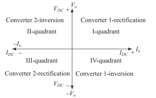
Four quadrant converters needed for complete DC motor control
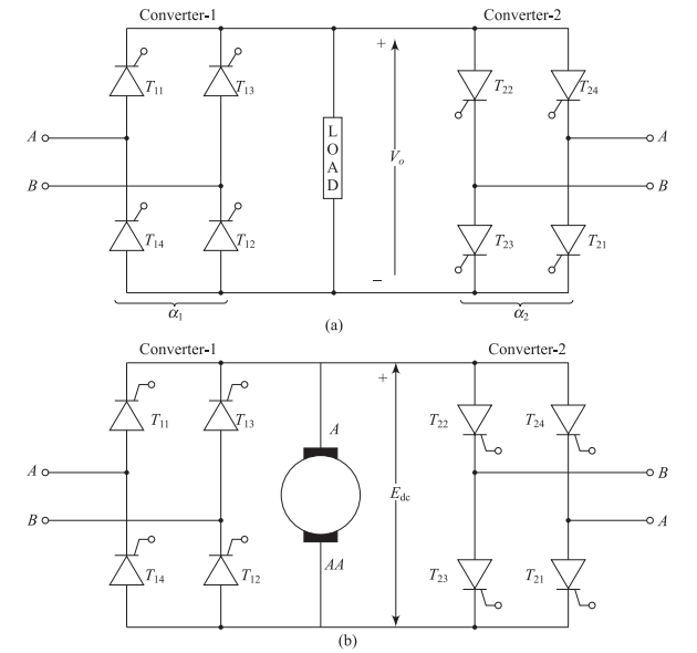
What are Dual Converters?
Dual converters consist of two fully controlled converters connected in anti-parallel (back-to-back) configuration to the load circuit.
Key Features:
-
Enable four-quadrant operation
-
Bidirectional voltage and current capability
-
Essential for reversible DC motor drives
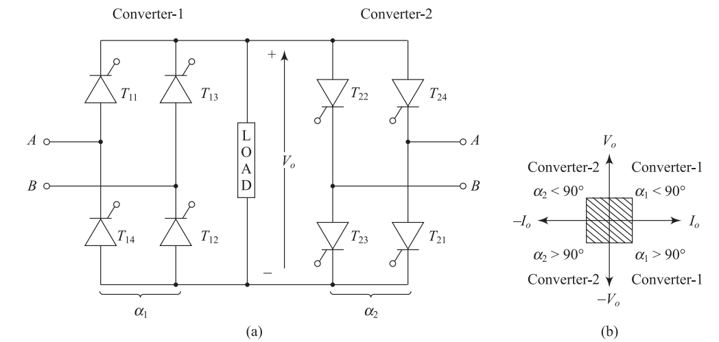
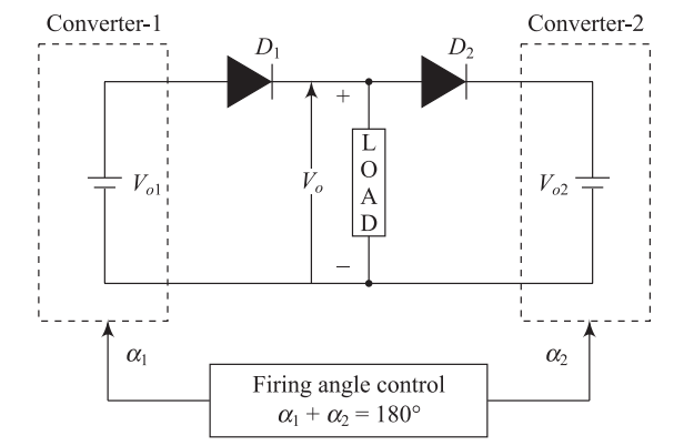
Equivalent Circuit Components
Basic Circuit Elements:
-
Two ideal two-quadrant converters (Converter-1 and Converter-2)
-
Two diodes (\(D_1\) and \(D_2\)) representing unidirectional current flow
-
Load (typically DC motor with back EMF and inductance)
Equivalent Model:
-
Converters modeled as controllable DC voltage sources
-
Diodes in series ensure unidirectional current capability
Assumptions for Analysis
Ideal Conditions:
-
Converters are ideal full converters
-
No ripple in output voltage (pure DC)
-
Negligible converter losses
-
Diodes \(D_1\) and \(D_2\) allow bidirectional current flow
-
Firing angles controlled by control voltage \(V_C\)
These assumptions simplify analysis and help understand fundamental operating principles.
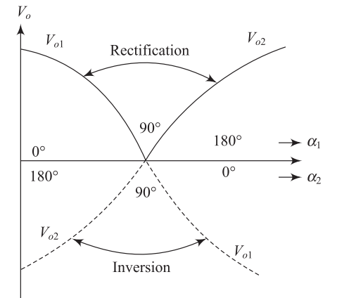
Output Voltage Relations
Voltage Characteristics:
-
\(V_{o1}\) and \(V_{o2}\): average output voltages of Converter-1 and Converter-2
-
Equal in magnitude but opposite in polarity
-
Drive current in opposite directions through the load
Operating Principle:
-
When one converter operates as controlled rectifier, the other operates as inverter
-
Positive group converter: Functions as rectifier
-
Negative group converter: Functions as inverter
Mathematical Relations
Average Output Voltages:
where for a single-phase full converter:
For an ideal converter: \(V_o = V_{o1} = -V_{o2}\)
Firing Angle Control
Control Strategy:
-
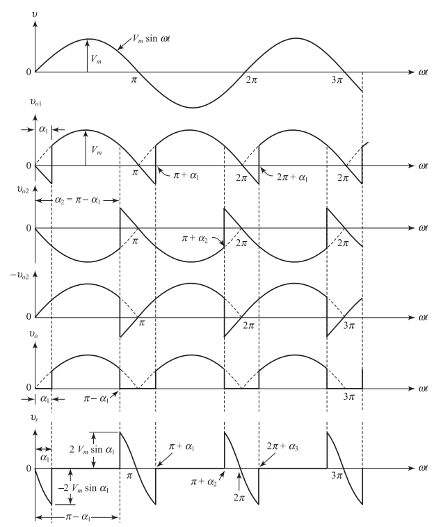
Firing angles varied maintaining: \(\alpha_1 + \alpha_2 = 180°\)
-
Ensures equal magnitude but opposite polarity voltages
Example:
-
If \(\alpha_1 = 30°\) \(\Rightarrow\) \(\alpha_2 = 150°\)
-
Converter-1: Rectifier mode
-
Converter-2: Inverter mode
-
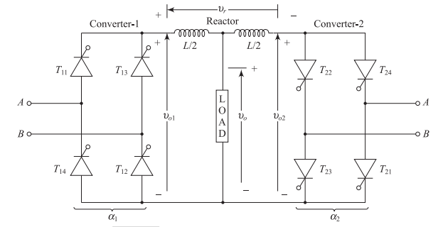
Issues in Practical Dual Converter
Challenge: Although average voltages are equal and opposite, instantaneous voltages differ.
Consequences:
-
Instantaneous output voltages \(V_{o1}\) and \(V_{o2}\) are out of phase
-
Voltage difference exists between the two converters
-
Large circulating current flows between converters (not through load)
Solutions:
-
Insert a reactor between converters to limit circulating current
-
Provide appropriate trigger pulses to avoid circulating current
Operating Modes
Two Operating Modes of Practical Dual Converter
Non-Circulating Current Mode
One converter active at a time
Circulating Current Mode
Both converters active simultaneously
Operating Principle
Key Characteristics:
-
Only one converter operates at any given time
-
Operating converter carries entire load current
-
Active converter receives firing pulses from triggering circuit
-
Idle converter blocked by removing triggering pulses
-
No circulating current flows
-
Reactor not required
Eliminates circulating current losses and reactor cost
Circuit Configuration
Converter Switching Process
Switching from Converter-1 to Converter-2:
-
Step 1: Remove firing pulses to thyristors of Converter-1
(OR increase firing angle \(\alpha_1\) to maximum value) -
Step 2: Load current decays to zero
-
Step 3: Wait for delay time (10–20 ms)
-
Step 4: Apply triggering pulses to thyristors of Converter-2
-
Step 5: Converter-2 switches ON
-
Step 6: Load current builds up in opposite direction
Delay time ensures reliable commutation of thyristors
Delay Time Requirement
Purpose of Delay Time:
-
Delay time: typically 10 to 20 ms
-
Delay between instant when Converter-1 turns OFF and Converter-2 turns ON
-
Ensures reliable commutation of all thyristors in Converter-1
If Converter-2 is triggered before Converter-1 completely turns off:
-
Large circulating current flows between converters
-
Potential damage to thyristors
-
System instability
Load Current Characteristics
Current Modes:
-
Load current may be continuous or discontinuous
-
Depends on load inductance and firing angle
Control Circuit Design:
-
Must provide satisfactory performance during both modes:
-
Continuous load current operation
-
Discontinuous load current operation
-
-
Proper current sensing and feedback mechanisms required
Operating Principle
Key Characteristics:
-
Both converters in operating condition simultaneously
-
One converter operates in controlled rectifier mode
-
Other operates in inverting mode
-
Reactor inserted between Converter-1 and Converter-2
-
Reactor limits amplitude of circulating current to acceptable value
Firing Angle Control
Control Law: \(\alpha_1 + \alpha_2 = 180°\) always satisfied
Example: If \(\alpha_1 = 45°\), then \(\alpha_2 = 135°\)
-
Converter-1 operates as controlled rectifier (\(\alpha_1 < 90°\))
-
Converter-2 operates as inverter (\(\alpha_2 > 90°\))
Voltage Characteristics:
-
Average values of \(V_{o1}\) and \(V_{o2}\) are equal
-
Instantaneous values of \(V_{o1}\) and \(V_{o2}\) differ
-
Voltage difference causes circulating current
Reactor (inductor) is essential to limit circulating current
Voltage Waveforms
Load Current Reversal
Reversal Process:
-
Load current reversed by interchanging roles of two converters
-
Converter-1 switches to inverter mode (\(\alpha_1 > 90°\))
-
Converter-2 switches to rectifier mode (\(\alpha_2 < 90°\))
-
Equation \(\alpha_1 + \alpha_2 = 180°\) always satisfied
-
Normal delay time (10–20 ms) not required
-
Instantaneous current reversal possible
-
Operation of this type of dual converter is faster
-
Better dynamic response
Non-Circulating vs Circulating Current Mode
| Parameter | Non-Circulating | Circulating |
|---|---|---|
| Converters active | One at a time | Both simultaneously |
| Circulating current | Zero | Present |
| Reactor required | No | Yes |
| Switching delay | 10–20 ms | Negligible |
| Response speed | Slower | Faster |
| Efficiency | Higher | Lower |
| THD rating | Lower | Higher |
| Cost | Lower | Higher |
Disadvantages
Major Drawbacks:
-
Reactor size and cost
-
Required to limit circulating current
-
Size and cost significantly high at high power levels
-
Adds weight and volume to the system
-
-
Low efficiency and power factor
-
Due to losses from circulating current
-
Increased copper and core losses in reactor
-
-
Higher thyristor current rating
-
Must handle both load current and circulating current
-
Increases device cost
-
-
Complex control system
-
Requires precise firing angle coordination
-
When to Use Circulating Current Mode
Despite disadvantages, circulating current mode dual converter is preferred when:
-
Load current needs to be reversed frequently
-
Fast response four-quadrant operation is required
-
Dynamic performance is critical
-
No time delay can be tolerated during reversal
Typical Applications:
-
Reversible rolling mill drives
-
High-performance servo systems
-
Rapid transit systems
Key Points
-
Dual converters enable four-quadrant operation for DC motor drives
-
Consist of two fully controlled converters connected back-to-back
-
Fundamental relation for ideal dual converter: \(\boxed{\alpha_1 + \alpha_2 = 180°}\)
-
Two operating modes available:
-
Non-circulating current mode: One converter active, no reactor
-
Circulating current mode: Both converters active, reactor required
-
-
Non-circulating mode: Higher efficiency, slower response
-
Circulating mode: Faster response, higher losses
-
Choice depends on application requirements
-
Essential for reversible DC motor control applications