Introduction to DIACs and TRIACs
-
AC power systems require devices that can conduct in both directions
-
Unidirectional devices (like SCR) need complex arrangements for AC control
-
Need for simple, cost-effective AC power control solutions
-
DIAC: DIode for Alternating Current - voltage-triggered switch
-
TRIAC: TRIode for Alternating Current - current-controlled switch
-
Both belong to the thyristor family of semiconductor switches
-
Commonly used together for AC phase control applications
-
Essential for residential and industrial AC power control
What is a DIAC?
-
A two-terminal semiconductor device with bidirectional switching capability
-
Also known as bidirectional avalanche diode or two-terminal AC switch
-
Terminals designated as Main Terminal-1 (MT1) and Main Terminal-2 (MT2)
-
Sometimes called Anode-I and Anode-II
-
No gate terminal - voltage-controlled only
-
Exhibits negative resistance in conduction region
-
Symmetric operation in both directions
-
Fixed breakover voltage (cannot be controlled)
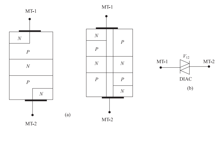
DIAC: Construction and Structure
Physical Structure:
-
PNPNP structure - arrangement of semiconductor layers
-
Symmetric construction with interchangeable terminals
-
Can conduct current in either direction
-
Fabricated using semiconductor technology
Operation Principle:
-
Works as bidirectional avalanche diode
-
Switches from OFF to ON state when breakover voltage is reached
DIAC: V-I Characteristics
Operating Regions:
-
Blocking state: When \(|V| < V_{\mathrm{BO}}\), only leakage current flows
-
Conduction state: When \(|V| \geq V_{\mathrm{BO}}\), device conducts with low resistance
-
Negative resistance: Current increases while voltage decreases during switching
-
Operations in quadrant I and III only
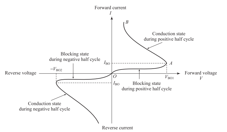
-
Breakover voltage (\(V_{\mathrm{BO}}\)): Typically around \(30\ \mathrm{V}\)
-
Voltage drop during conduction: About \(3\ \mathrm{V}\)
-
Current limiting: Amplitude limited by external resistance
DIAC: Switching Mechanism
-
Applied voltage increases across DIAC terminals
-
When \(|V| \geq V_{\mathrm{BO}}\), avalanche breakdown occurs
-
Device switches to low-impedance state (negative resistance)
-
Current amplitude is limited by external resistance
-
Device turns OFF when current drops below holding current
-
No gate control available - purely voltage and current dependent
-
Natural turn-OFF at current zero crossing in AC circuits
-
DIAC has fixed switching characteristics
-
Cannot be controlled once breakdown voltage is reached
-
Firing angle is fixed for a given supply voltage
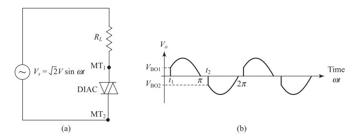
DIAC Circuit Operation
-
DIAC turns ON when supply voltage reaches breakover voltage
-
During positive half-cycle: Conducts when \(v > V_{\mathrm{BO}}\)
-
During negative half-cycle: Conducts when \(v < -V_{\mathrm{BO}}\)
-
Fixed firing angle based on \(V_{\mathrm{BO}}\) and supply voltage
-
Primarily used as triggering device for TRIAC
-
Two-terminal AC switch applications
-
Oscillator circuits
-
Simple AC control circuits
What is a TRIAC?
-
Three-terminal semiconductor device for bidirectional AC control
-
Equivalent to two SCRs connected anti-parallel with common gate
-
Enables variable power control in AC circuits
-
Can handle both directions of current flow
-
Single device instead of two anti-parallel SCRs
-
Simplified gate drive circuitry
-
Reduced component count and cost
-
Better thermal management
-
MT1: Main Terminal 1 (reference terminal)
-
MT2: Main Terminal 2
-
G: Gate (control terminal near MT1)
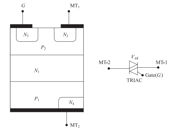
TRIAC: Structure and Operating Principle
-
Complex semiconductor structure
-
Multiple current paths enable bidirectional conduction
-
Gate located near MT1 for control
-
Asymmetric structure leads to different sensitivities
-
Works like two SCRs sharing a common gate
-
Gate current triggers the device based on MT2 polarity
-
Once triggered, gate loses control (latching behavior)
-
Device turns OFF at natural current zero crossing
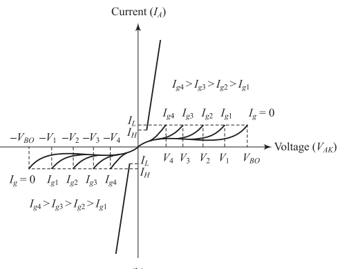
TRIAC: V-I Characteristics
-
First quadrant: MT2 positive with respect to MT1
-
Third quadrant: MT2 negative with respect to MT1
-
Can be triggered with or without gate signal
-
Multiple characteristic curves for different gate currents
-
Breakover voltage decreases with increasing gate current
-
Forward voltage drop during conduction is small
-
Gate control allows variable firing angle
-
Current ratings: 1 A to 300 A, Voltage ratings: up to 1200 V
TRIAC: Four Operating Modes
| Mode | MT2 | Gate | Sensitivity |
|---|---|---|---|
| 1 | Positive | Positive | Most sensitive |
| 2 | Positive | Negative | Less sensitive |
| 3 | Negative | Negative | More sensitive |
| 4 | Negative | Positive | Least sensitive |
-
Modes 1 and 3 are predominantly used (higher sensitivity)
-
Mode 2 and Mode 4 are less commonly used
-
Gate current requirement varies with operating mode
-
Commercial TRIACs optimized for efficient operation
TRIAC Operating Mode Details
-
Most sensitive mode of operation
-
Gate current flows from gate to MT1
-
Structure operates similar to normal SCR
-
Minimum gate current required for triggering
-
Second most sensitive mode
-
Remote gate effect through auxiliary structure
-
Slightly higher gate current needed than Mode 1
-
Good sensitivity for practical applications
-
Mode 2: MT2 positive, Gate negative - Less sensitive
-
Mode 4: MT2 negative, Gate positive - Least sensitive, rarely used
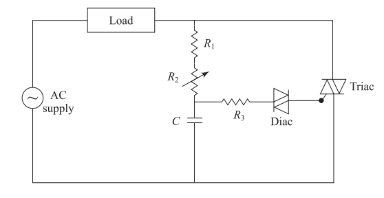
Basic DIAC-TRIAC Phase Control Circuit
-
\(R_1\): Fixed resistor for protection
-
\(R_2\): Variable resistor for firing angle control
-
\(C\): Timing capacitor
-
\(R_3\): Gate current limiting resistor
-
Capacitor charges through \((R_1 + R_2)\)
-
When capacitor voltage = DIAC breakover voltage, DIAC conducts
-
Capacitor discharges through DIAC and TRIAC gate
-
TRIAC turns ON and conducts until current zero
-
Practical firing angle range: \(10^\circ\) – \(170^\circ\)
-
Variable \(R_2\) controls charging time and thus firing angle
Circuit Operation Analysis
-
Charging phase: Capacitor \(C\) charges through \((R_1 + R_2)\)
-
Trigger point: When \(v_C = V_{\mathrm{BO}}\) of DIAC, DIAC conducts
-
Gate pulse: Capacitor rapidly discharges through DIAC to TRIAC gate
-
TRIAC conduction: TRIAC turns ON and conducts until current zero
-
Reset: Process repeats for next half-cycle
-
Small \(R_2\): Fast charging → Early firing → High power output
-
Large \(R_2\): Slow charging → Late firing → Low power output
-
Charging time constant: \(\tau = (R_1 + R_2) \times C\)
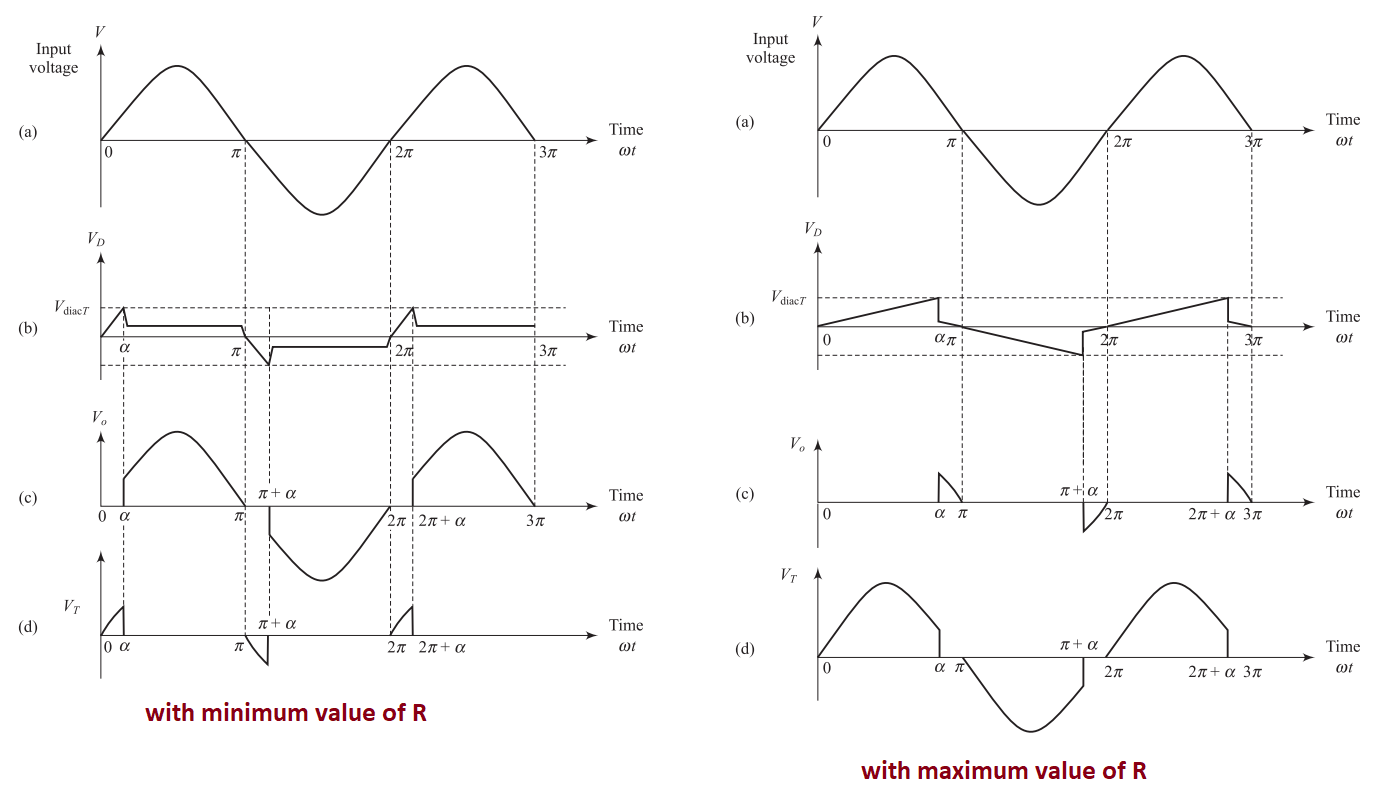
TRIAC Firing Circuit Waveforms
-
Capacitor charges quickly
-
DIAC fires early in the half-cycle
-
TRIAC conducts for longer duration
-
Higher power delivered to load
-
Capacitor charges slowly
-
DIAC fires late in the half-cycle
-
TRIAC conducts for shorter duration
-
Lower power delivered to load
-
Basic circuit produces unsymmetrical waveforms
-
Due to TRIAC characteristics and capacitor hysteresis
-
Capacitor retains some charge when input voltage becomes zero
-
Additional components needed for symmetrical operation
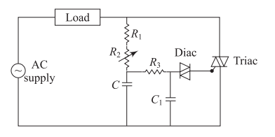
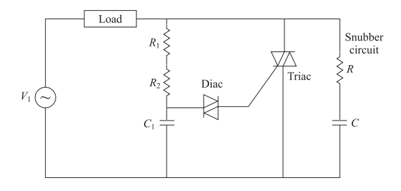
Improved TRIAC Firing Circuit
-
Asymmetric triggering due to capacitor hysteresis
-
Different positive and negative half-cycle behavior
-
Unequal power delivery in both half-cycles
-
Additional \(R_3\) and \(C_1\): Provide symmetrical discharge path
-
Snubber circuit: R-C network for protection against voltage spikes
-
Better waveform symmetry: Equal conduction in both half-cycles
-
Commercial circuits: Include EMI filters and protection elements
TRIAC Protection Requirements
-
Purpose: Limit \(dv/dt\) to prevent false triggering
-
Components: Small R-C network across TRIAC
-
Protection: Against voltage transients and spikes
-
Fuses: Overcurrent protection for safety
-
Snubber circuits: Essential for inductive loads
-
EMI suppression: Filters to reduce electromagnetic interference
-
Thermal management: Heat sinks for high-power applications
Applications of DIAC-TRIAC Circuits
-
Light dimmers: Variable lighting control
-
Fan speed controllers: Ceiling fans and ventilation
-
Heating control: Electric heaters and cooking appliances
-
Motor control: Single-phase AC motors
-
Temperature controllers: Process heating control
-
Motor soft starters: Reduced inrush current
-
Static AC switches: Contactless switching
-
Heat control systems: Industrial heating applications
-
Resistive loads: Excellent performance (heaters, lamps)
-
Inductive loads: Requires snubber circuits (motors, transformers)
-
Universal motors: Good performance for speed control
DIAC vs TRIAC: Complete Comparison
| Parameter | DIAC | TRIAC |
|---|---|---|
| Number of terminals | 2 (MT1, MT2) | 3 (MT1, MT2, Gate) |
| Control method | Voltage-triggered only | Gate current controlled |
| Triggering | Fixed at \(V_{\mathrm{BO}} \approx 30V\) | Variable with gate signal |
| Power handling | Low (mW range) | High (up to several kW) |
| Primary function | Trigger pulse generation | AC power control |
| Turn-off method | Current below holding value | Current zero crossing |
| Applications | TRIAC triggering | Motor control, heating, lighting |
| Voltage rating | Around 30V | Up to 1200V |
| Current rating | Few hundred mA | Up to 300A |
Key Learning Points
-
Two-terminal bidirectional avalanche diode
-
Fixed breakover voltage around 30V
-
Primarily used for triggering TRIACs
-
No control over switching once breakover voltage is reached
-
Three-terminal bidirectional thyristor
-
Gate-controlled switching for variable power control
-
Four operating modes with different sensitivities
-
Widely used for AC power control applications
-
DIAC-TRIAC combination provides simple AC control
-
Protection circuits essential for reliable operation
-
Asymmetry issues require careful circuit design
-
Snubber circuits needed for inductive loads