Introduction
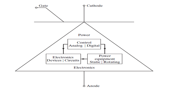
- Power Electronics: Power + Electronics + Control
- Power: the static and rotating power equipment for the G, T, & D of electric energy
- Electronics: the solid-state devices and circuits for signal processing to meet the desired control objectives
- Control: the steady-state and dynamic characteristics of closed-loop systems
- Power electronics may be defined as the application of solid-state electronics for the control and conversion of electric power
- Based primarily on switching of the power semiconductor devices.
- Power semiconductors improves power-handling capabilities and switching speed of the power devices tremendously.
- Microprocessors has a great impact on control strategy for the power semiconductor devices
-
Power electronics \(\Rightarrow\) power semiconductors (muscles) + microelectronics (brain)
-
current direction from anode (A) to cathode (K)
-
Gate (G) to turn on or off the signal
-
without gate signal remains off-state (open circuit) and can withstand a voltage across the terminals A and K.
Numerous Applications
| Advertising | Air-conditioning | Aircraft power |
| Alarms | Appliances | Audio amplifiers |
| Battery charger | Blenders | Blowers |
| Boilers | Burglar alarms | Cement kiln |
| Chemical processing | Clothes dryers | Computers |
| Conveyors | Cranes and hoists | Dimmers |
| Displays | Electric blankets | Particle accelerators |
| Electric dryers | Electric fans | Electric vehicles |
| Electromagnets | Electroplating | Electronic ignition |
| Precipitators | Elevators | Fans |
| Flashers | Food mixers | Food warmer trays |
| Forklift trucks | Furnaces | Games |
| Door openers | Gas turbine | Generator exciters |
| Grinders | Power tools | Heat controls |
| Lighting | HVDC | Induction heating |
| Laser power | Latching relays | Light dimmers |
| Light flashers | Linear induction motor | Locomotives |
| Machine tools | Magnetic recordings | Mass transits |
History of Power Electronics
-
1900 - Introduction of the mercury arc rectifier
-
Until 1950s - Several devices for power control, such as metal tank rectifier, grid-controlled vacuum-tube rectifier, ignitron, phanotron, and thyratron
-
1948 - First revolution: Invention of the silicon transistor
-
Bell Telephone Laboratories by Bardeen, Brattain, and Schokley
-
-
Modern microelectronics evolved over the years from silicon semiconductors
-
1956 - Major breakthrough by Bell Laboratories: invention of the PNPN triggering transistor, called thyristor or silicon-controlled rectifier (SCR).
-
1958 - Commercial thyristor by the General Electric Company
-
Due to the fusion of power electronics, the muscle, with microelectronics, the brain, many potential applications of power electronics are now emerging, and this trend will continue.
Power Electronic Circuits
-
Control of Electric Power:
-
For effective control of electric power or power conditioning, it is essential to convert electric power from one form to another.
-
-
Switching Characteristics of Power Devices:
-
The switching characteristics of power devices play a crucial role in facilitating these power conversions.
-
-
Static Power Converters:
-
Static power converters are responsible for performing the functions of power conversions.
-
-
Converter as a Switching Matrix:
-
Conceptually, a converter can be envisioned as a switching matrix.
-
In this matrix, one or more switches are turned on and connected to the supply source.
-
The purpose is to achieve the desired output voltage or current through controlled switching actions.
-
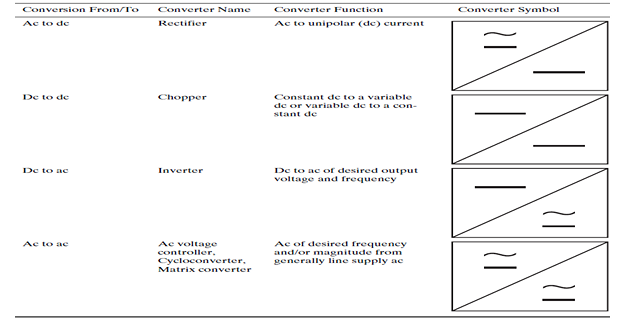
Types of Power Electronic Circuits
-
Power electronics circuits can be categorized into six types.
-
Diode rectifiers
-
Dc–dc converters (dc choppers)
-
Dc–ac converters (inverters)
-
Ac–dc converters (controlled rectifiers)
-
Ac–ac converters (ac voltage controllers or Cycloconverters)
-
Static switches
-
-
The switching devices in the following converters are employed to demonstrate fundamental principles.
-
The switching action within a converter may involve multiple devices.
-
The selection of a specific device is contingent upon the voltage, current, and speed requirements of the converter.
Diode rectifiers:
-
Converts ac voltage into a fixed dc voltage
-
A diode conducts when its anode voltage \(>\) cathode voltage, and it offers a very small voltage drop, ideally zero, but typically 0.7 V.
-
Behaves as an open circuit when its cathode voltage \(>\) anode voltage, offering a very high resistance, ideally infinite, but typically 10 \(k\Omega\).
-
Output voltage is a pulsating dc, but it is distorted and contains harmonics.
-
Input voltage could be either single phase or three phase.

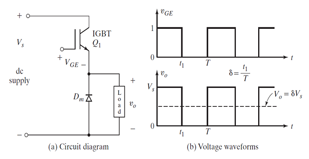
Dc–dc converters:
-
Also known as chopper or switching regulator
-
When transistor \(Q_1\) is turned on by applying a gate voltage \(V_{GE}\), the dc supply is connected to the load and the instantaneous output voltage is \(v_0=+V_s\).
-
\(Q_1\) is turned off by removing \(V_{GE}\), the dc supply is disconnected from the load and \(v_0=0\).
-
Average output voltage can be varied by controlling the duty cycle (\(\delta\)) and controlled by varying the conduction time \(t\) of \(Q_1\).
-
\(T\) is the chopping period, then \(t_1 = \delta \cdot T\).
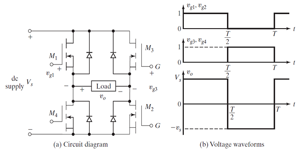
Dc–ac converters:
-
Also known as an inverter
-
When MOSFETs \(M_1\) and \(M_2\) are turned on by applying gate voltages, the dc supply voltage \(V_s\) appears across the load and the instantaneous output voltage is \(v_o = +V_s\).
-
When \(M_3\) and \(M_4\) are turned on by applying gate voltages, the \(V_s\) appears across the load in the opposite direction, \(v_o = -V_s\).
-
If \(M_1\) and \(M_2\) conduct for one half of a period and \(M_3\) and \(M_4\) conduct for the other half, the output voltage is of the alternating form.
-
The rms value of the output voltage becomes \(V_{o(\text{rms})} = V_s\)
-
However, the output voltage contains harmonics which could be filtered out before supplying to the load.
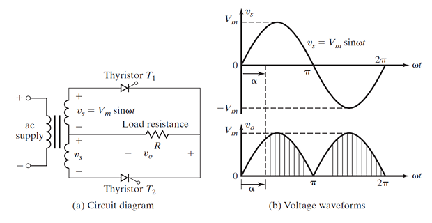
Ac–dc converters:
-
Also known as controlled rectifiers
-
When thyristor \(T_1\) is turned on at a delay angle of \(\omega t=\alpha\), the supply voltage appears across load and \(T_{1}\) is turned off automatically when its current falls to zero at \(\omega t=\pi.\)
-
When \(T_{2}\) is turned on at a delay angle of \(\omega t=\pi+\alpha\), the negative part of the supply voltage appears the across the load in the positive direction and \(T_{2}\) is turned off automatically when its current falls to zero at \(\omega t=2\pi.\)
-
The average output voltage can be found from \(V_{o(\mathrm{AVG})}=(1+\cos\alpha)V_{m}/\pi\).
-
The average value of the output voltage \(v_{0}\) can be controlled by varying the conduction time of thyristors or firing delay angle, \(\alpha\).
-
The input could be a single- or three-phase source.
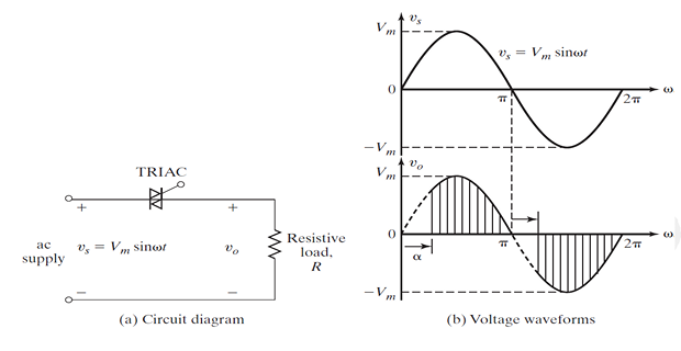
Ac–ac converters
-
Also known as ac voltage controllers
-
To obtain a variable ac output voltage \(v_o\) from a fixed ac source
-
A TRIAC allows a current flow in both directions
-
It activates when a gate voltage is applied at \(\omega t = \alpha\) for positive current flow, and at \(\omega t = \pi + \alpha\) for negative current flow.
-
\(v_o\) is controlled by varying the conduction time or firing delay angle \(\alpha\) of the TRIAC.
-
Power devices can function as static switches or contactors, operating with either AC or DC supplies.
-
These switches are termed AC static switches or DC switches.
-
The design can be divided into four parts:
-
Design of power circuits
-
Protection of power devices
-
Determination of control strategy
-
Design of logic and gating circuits
-
-
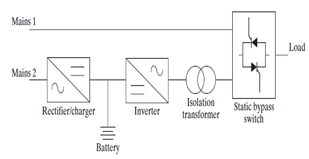
Multiple conversion stages are frequently linked together to generate the intended output.
-
Mains 1 delivers the standard AC supply to the load via the static bypass.
-
The AC to DC converter charges the backup battery from mains 2.
-
The DC to AC converter provides emergency power to the load through an isolating transformer.
-
Typically, mains 1 and mains 2 are connected to the same AC supply.
-
Power Diodes and Switched RLC Circuits
-
Diode Rectifiers
-
Power Transistors (MOSFETs, JFETs, IGBTs)
-
DC–DC Converters (or Choppers)
-
DC–AC Converters (or Inverters)
-
Resonant Pulse Inverters
-
Multilevel Inverters
-
Thyristors
-
Controlled Rectifiers
-
AC Voltage Controllers
Reference Text Books