Introduction
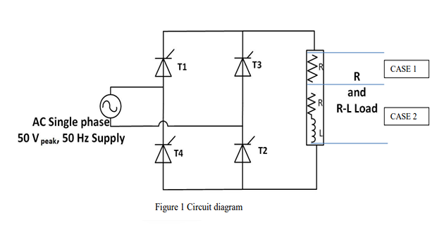
This experiment studies the single-phase fully controlled converter using four thyristors (SCRs) in a bridge configuration. The firing angle α controls the mean DC output voltage continuously from maximum (α = 0°) to zero (α = 180°), enabling precise power regulation.
Theory
A fully controlled converter uses thyristors only. With R load: single-quadrant operation (Vo ≥ 0, Io ≥ 0). With RL load: two-quadrant operation (Vo can be negative, Io ≥ 0 always).
Simulation — R Load (Problem 1)
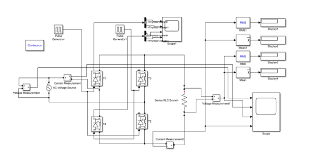
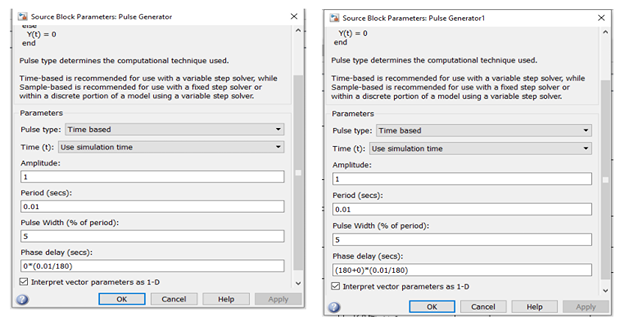
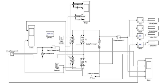
Implement the 1-phase fully controlled full-wave rectifier with R = 12.5 Ω. Input: 50 V peak (35.35 V RMS), 50 Hz. Observe output waveforms at firing angles 0°, 45°, 90°, 135°.
Simulation — RL Load (Problem 2)
Add L = 6 mH in series with R = 12.5 Ω. Observe the effect of inductance on output waveforms at the same firing angles.
Hardware — R Load
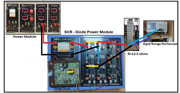
- Connect circuit as in Fig. 6 (R = 12.5 Ω). Switch ON 3φ supply MCB.
- Switch ON POWER MODULE and SCR–Diode module MCBs. Set voltage to 35.35 V RMS.
- Switch ON driver power switch. Connect CRO probes across R load.
- Vary firing angle and record results per the observation table below.
Hardware — RL Load
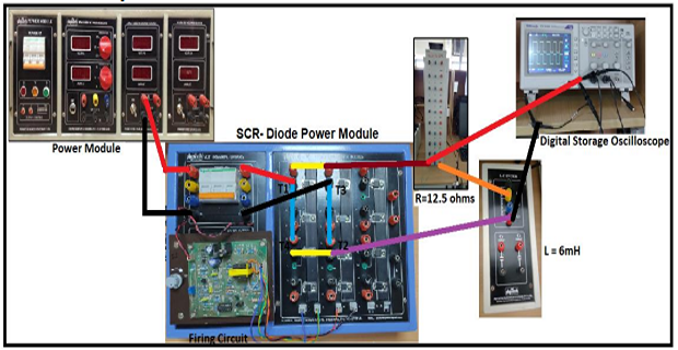
- Connect circuit as in Fig. 7 (R = 12.5 Ω, L = 6 mH). Repeat steps 1–4 from R Load procedure.
- Connect CRO probes across both R and L. Note the effect of inductance on firing angle range.
Results
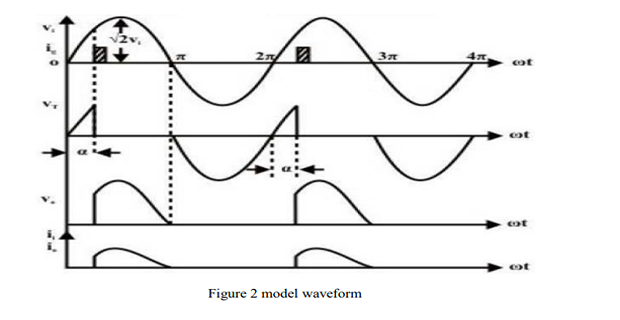
Required waveforms to attach: Input Voltage, Input Current, Output Voltage, Output Current, Thyristor Voltage, Thyristor Current (Simulink at α = 45°; DSO at α = 45°).
I) R-Load — Simulation Observation Table
| S.No | Firing Angle (time) | Firing Angle (degrees) | Vavg (V) | Vrms (V) | Iavg (A) | Irms (A) |
|---|---|---|---|---|---|---|
| 1. | 0 ms | 0° | ||||
| 2. | 2.5 ms | 45° | ||||
| 3. | 5 ms | 90° | ||||
| 4. | 7.5 ms | 135° |
I) R-Load — Hardware Observation Table
| S.No | Firing Angle (time) | Firing Angle (degrees) | Vavg (V) | Vrms (V) |
|---|---|---|---|---|
| 1. | 0 ms | 0° | ||
| 2. | 2.5 ms | 45° | ||
| 3. | 5 ms | 90° | ||
| 4. | 7.5 ms | 135° |
II) RL-Load — Simulation Observation Table
| S.No | Firing Angle (time) | Firing Angle (degrees) | Vavg (V) | Vrms (V) | Iavg (A) | Irms (A) |
|---|---|---|---|---|---|---|
| 1. | 0 ms | 0° | ||||
| 2. | 2.5 ms | 45° | ||||
| 3. | 5 ms | 90° | ||||
| 4. | 7.5 ms | 135° |
II) RL-Load — Hardware Observation Table
| S.No | Firing Angle (time) | Firing Angle (degrees) | Vavg (V) | Vrms (V) |
|---|---|---|---|---|
| 1. | 0 ms | 0° | ||
| 2. | 2.5 ms | 45° | ||
| 3. | 5 ms | 90° | ||
| 4. | 7.5 ms | 135° |