Introduction
This experiment analyses the effect of a smoothing (filter) capacitor on rectified output voltage for both single-phase and three-phase uncontrolled rectifiers. Adding a capacitor across the load significantly reduces ripple and raises the mean DC output voltage.
Smoothing Capacitor Theory
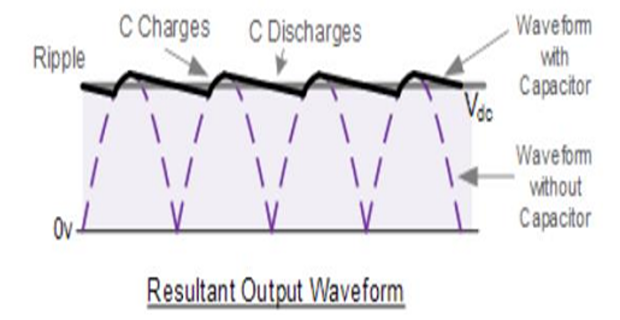
The capacitor charges to the peak voltage when diodes conduct and discharges through the load when diodes are reverse-biased. Two key selection parameters:
Must be higher than the no-load peak output voltage of the rectifier to prevent dielectric breakdown.
Larger capacitance ⇒ lower ripple voltage. Target: ripple < 100 mV peak-to-peak for practical DC supplies.
Simulation — Single-Phase with C Filter
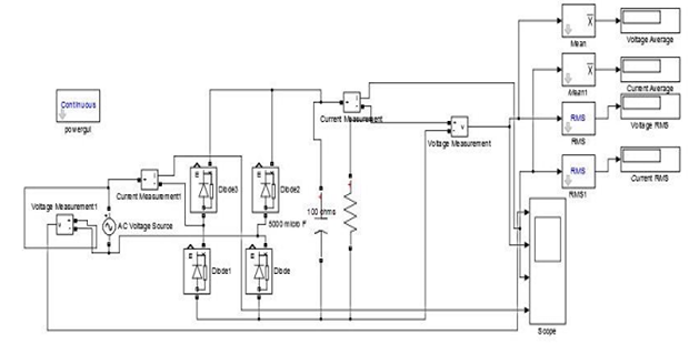
Implement 1-phase uncontrolled full-wave rectifier with C = 5000 μF in parallel with R = 100 Ω. Input: 50 V peak (35.35 V RMS), 50 Hz. Observe output voltage changes.
Simulation — Three-Phase with C Filter
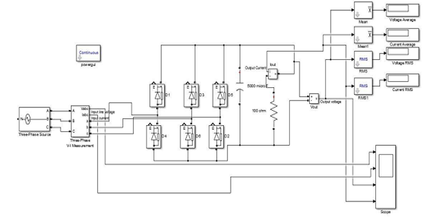
Implement 3-phase uncontrolled full-wave rectifier with C = 5000 μF and R = 100 Ω. Input: \(V_{LL,rms} = 61.2\text{ V}\), 50 Hz. Observe and compare with single-phase results.
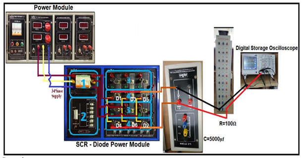
Hardware — Single-Phase with C Filter
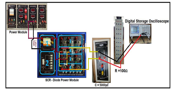
- Connect circuit as in Fig. 4 (R = 100 Ω, C = 5000 μF). Switch ON 3φ supply MCB.
- Switch ON POWER MODULE and SCR–Diode module MCBs. Set voltage to 35.35 V RMS.
- Connect CRO probes across R load. Observe output voltage waveforms and FFT.
Hardware — Three-Phase with C Filter
- Connect circuit as in Fig. 5. Switch ON 3φ supply MCB.
- Set voltage to 61.2 V RMS. Connect CRO probes and observe waveforms.
Results
Attach waveforms: Output Voltage, Output Current, Input Voltage, Input Current for both single-phase and three-phase cases (Simulink and DSO).
Performance Parameters — Simulation
| Parameter | Single Phase | Three Phase |
|---|---|---|
| VRMS (V) | ||
| IRMS (A) | ||
| VAVG (V) | ||
| IAVG (A) | ||
| Form Factor | ||
| Ripple Factor |
Performance Parameters — Hardware
| Parameter | Single Phase | Three Phase |
|---|---|---|
| VRMS (V) | ||
| VAVG (V) | ||
| Form Factor | ||
| Ripple Factor |