Aim & Tools
To study the operation of DC-DC converters (Buck, Boost, Buck-Boost) using MATLAB Simulink. The duty cycle D is varied from 20% to 80% and simulated output voltage is compared with theoretical values.
Output voltage is lower than input. \(V_o = D \cdot V_{in}\). Used in voltage regulators, battery chargers.
Output voltage is higher than input. \(V_o = V_{in}/(1-D)\). Used in PV inverters, LED drivers.
Output magnitude can be higher or lower, but polarity is inverted. \(V_o = D V_{in}/(1-D)\cdot(-1)\). Used in battery systems.
Theory — Converter Equations
Simulation Procedure
- Construct the converter circuit in MATLAB Simulink.
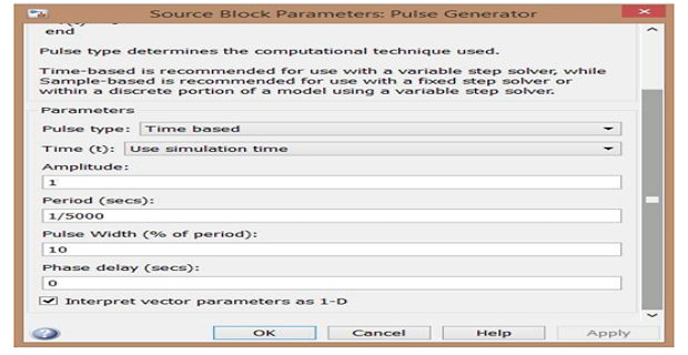
- Use a Pulse Generator block to generate gate pulses for the IGBT switch.
- Configure the pulse generator: Period = switching period T; Pulse Width = D × T × 100%.
- Vary the duty cycle (Pulse Width) as per the observation table.
- Record simulated output voltage and compare with theoretical formula.
Buck Converter


Buck Converter Observation Table
| S.No | Vin (V) | Duty Cycle D (%) | Vo,calculated (V) | Vo,simulated (V) |
|---|---|---|---|---|
| 1. | 20 | |||
| 2. | 40 | |||
| 3. | 60 | |||
| 4. | 80 |
Boost Converter

Boost Converter Observation Table
| S.No | Vin (V) | Duty Cycle D (%) | Vo,calculated (V) | Vo,simulated (V) |
|---|---|---|---|---|
| 1. | 20 | |||
| 2. | 40 | |||
| 3. | 60 | |||
| 4. | 80 |
Buck-Boost Converter

Buck-Boost Converter Observation Table
| S.No | Vin (V) | Duty Cycle D (%) | Vo,calculated (V) | Vo,simulated (V) |
|---|---|---|---|---|
| 1. | 20 | |||
| 2. | 40 | |||
| 3. | 60 | |||
| 4. | 80 |
Results
For each converter, attach: (1) MATLAB Simulink circuit diagram (2) Simulated waveforms at 40% duty cycle: Source voltage and current, Output Voltage and Current, Voltage across IGBT (3) Completed observation tables comparing calculated vs simulated output voltages.