Introduction
This experiment studies the single-phase phase-angle controlled AC-AC voltage converter using a TRIAC. The TRIAC conducts on both polarities of the AC supply, enabling bidirectional power control. Applications include light dimmers, motor speed control, and heating element regulation.
Theory
AC-to-AC voltage converters regulate output voltage by allowing portions of the input sinusoid to reach the load while blocking the rest. They are called Phase Angle Controlled (PAC) AC-AC converters or AC choppers. The TRIAC acts on both polarities, making it the natural choice for bidirectional control.

Output voltage follows input sinusoid from α to π, and π+α to 2π. No reactive energy storage.

Inductive load extends conduction beyond voltage zero-crossing. The minimum firing angle is limited by load power factor angle φ.


Simulation — R Load
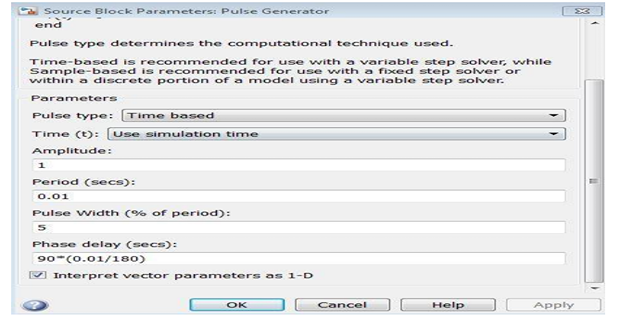
Implement the 1-phase phase-controlled bidirectional AC-AC controller with R = 12.5 Ω. Input: 50 V peak (35.35 V RMS), 50 Hz. Observe output voltage waveforms at α = 0°, 45°, 90°, 120°.


Simulation — RL Load
Implement with R = 12.5 Ω, L = 6 mH. Observe changes in output waveform — note the extended conduction due to inductive load.

Hardware — R Load

- Connect circuit as in Fig. 9 (R = 12.5 Ω). Switch ON 3φ supply and POWER MODULE MCBs.
- Switch ON SCR-Diode Power Module MCB. Increase voltage to 35.35 V RMS.
- Switch ON driver power switch. Connect CRO probes across R load.
- Vary firing angle and record RMS output voltage at each setting.
Hardware — RL Load

- Connect circuit as in Fig. 10 (R = 12.5 Ω, L = 6 mH). Repeat hardware steps 1–4 from R-load procedure.
- Note minimum firing angle limited by load power factor angle φ = arctan(ωL/R).
Results
I) R-Load — Simulation
| S.No | Firing Angle (time) | Firing Angle (degrees) | Vrms Output (V) | Irms Output (A) |
|---|---|---|---|---|
| 1. | 0 ms | 0° | ||
| 2. | 2.5 ms | 45° | ||
| 3. | 5 ms | 90° | ||
| 4. | 6.66 ms | 120° |
I) R-Load — Hardware
| S.No | Firing Angle (time) | Firing Angle (degrees) | Vrms Output (V) |
|---|---|---|---|
| 1. | 0 ms | 0° | |
| 2. | 2.5 ms | 45° | |
| 3. | 5 ms | 90° | |
| 4. | 6.66 ms | 120° |
II) RL-Load — Simulation
| S.No | Firing Angle (time) | Firing Angle (degrees) | Vrms Output (V) | Irms Output (A) |
|---|---|---|---|---|
| 1. | 0 ms | 0° | ||
| 2. | 2.5 ms | 45° | ||
| 3. | 5 ms | 90° | ||
| 4. | 6.66 ms | 120° |
II) RL-Load — Hardware
| S.No | Firing Angle (time) | Firing Angle (degrees) | Vrms Output (V) |
|---|---|---|---|
| 1. | 0 ms | 0° | |
| 2. | 2.5 ms | 45° | |
| 3. | 5 ms | 90° | |
| 4. | 6.66 ms | 120° |