1-Mark Questions
QQuestion 1 1 Mark
The geometric mean radius of a conductor, having four equal strands with each strand of radius \('r'\), as shown in the figure below, is
\begin{figure}[h] \centering
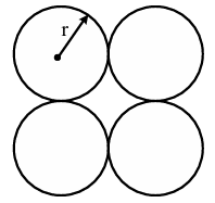
\caption{Four-strand conductor configuration for Question 14} \end{figure}
\vspace{0.3in}
AOptions
- \(4r\)
- \(1.414r\)
- \(2r\)
- \(1.723r\)
SSolution
For a conductor with multiple strands, the Geometric Mean Radius (GMR) is calculated using:
where \(n\) is the number of strands.
For a stranded conductor, we need to find the geometric mean of all possible distances:
- Self GMR of each strand: \(r' = 0.7788r\) (for a solid circular conductor)
- Mutual distances between strands
For 4 strands arranged in a square pattern:
Assuming the strands are arranged in a square with center-to-center distance \(d\) between adjacent strands. For a bundled conductor where strands touch each other, \(d = 2r\).
The GMR of the composite conductor:
For one strand, considering distances to other three strands:
- Self GMR: \(r' = 0.7788r\)
- Distance to adjacent strands: \(d_{12} = d_{14} = 2r\)
- Distance to diagonal strand: \(d_{13} = 2\sqrt{2}r\)
For the entire 4-strand bundle:
Therefore, \(GMR = 1.723r\)
Alternative approach using standard formula:
For \(n\) identical strands arranged symmetrically, the GMR is:
For 4 strands in square configuration with each strand of radius \(r\):
This is a standard result for 4-strand ACSR conductors.
Correct answer: (D) \(1.723r\)
QQuestion 2 1 Mark
The valid positive, negative and zero sequence impedances (in p.u.), respectively, for a 220 kV, fully transposed three-phase transmission line, from the given choices are
\vspace{0.3in}
AOptions
- \(1.1, 0.15\) and \(0.08\)
- \(0.15, 0.15\) and \(0.35\)
- \(0.2, 0.2\) and \(0.2\)
- \(0.1, 0.3\) and \(0.1\)
SSolution
For a fully transposed three-phase transmission line, we need to understand the characteristics of sequence impedances:
Key Concepts:
1. Positive Sequence Impedance (\(Z_1\)):
- This is the normal operating impedance of the line
- Depends on conductor spacing, conductor radius, and frequency
- Typically in the range of 0.1 to 0.5 p.u. for transmission lines
2. Negative Sequence Impedance (\(Z_2\)):
- For a fully transposed, symmetric transmission line
- \(Z_2 = Z_1\) (always equal to positive sequence impedance)
- This is because the line geometry is symmetric and balanced
3. Zero Sequence Impedance (\(Z_0\)):
- Always different from \(Z_1\) and \(Z_2\)
- Typically \(Z_0 > Z_1\) (often 2 to 4 times larger)
- Depends on ground return path
- For overhead lines: \(Z_0 = 3Z_s + Z_m\) where \(Z_s\) is self impedance and \(Z_m\) is mutual impedance
Analysis of options:
Option (A): \(Z_1 = 1.1\), \(Z_2 = 0.15\), \(Z_0 = 0.08\)
- \(Z_1 \neq Z_2\) âœ (violates transposition property)
- \(Z_0 < Z_1\) âœ (typically \(Z_0 > Z_1\))
- Invalid
Option (B): \(Z_1 = 0.15\), \(Z_2 = 0.15\), \(Z_0 = 0.35\)
- \(Z_1 = Z_2\) ✓ (satisfies transposition)
- \(Z_0 > Z_1\) ✓ (correct relationship)
- \(Z_0 \approx 2.33 \times Z_1\) (reasonable ratio)
- Valid ✓
Option (C): \(Z_1 = 0.2\), \(Z_2 = 0.2\), \(Z_0 = 0.2\)
- \(Z_1 = Z_2\) ✓
- \(Z_0 = Z_1\) âœ (not typical for overhead lines)
- This could only occur for special configurations like underground cables
- Not typical for 220 kV overhead transmission line
- Invalid for this case
Option (D): \(Z_1 = 0.1\), \(Z_2 = 0.3\), \(Z_0 = 0.1\)
- \(Z_1 \neq Z_2\) âœ (violates transposition property)
- Invalid
Conclusion:
For a fully transposed three-phase transmission line:
- \(Z_1 = Z_2\) (mandatory condition)
- \(Z_0 > Z_1\) (typical for overhead lines)
- Only option (B) satisfies both conditions
Correct answer: (B) \(0.15, 0.15\) and \(0.35\)
QQuestion 3 1 Mark
In the circuit shown below, a three-phase star-connected unbalanced load is connected to a balanced three-phase supply of \(100\sqrt{3}\) V with phase sequence \(ABC\). The star connected load has \(Z_A = 10~\Omega\) and \(Z_B = 20\angle 60°~\Omega\). The value of \(Z_C\) in \(\Omega\), for which the voltage difference across the nodes \(n\) and \(n'\) is zero, is
\begin{figure}[h] \centering
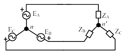
\caption{Three-phase unbalanced load circuit for Question 21} \end{figure}
\vspace{0.3in}
AOptions
- \(20\angle -30°\)
- \(20\angle 30°\)
- \(20\angle -60°\)
- \(20\angle 60°\)
SSolution
Given:
- Line voltage: \(V_L = 100\sqrt{3}\) V
- Phase sequence: ABC
- \(Z_A = 10~\Omega\) (purely resistive)
- \(Z_B = 20\angle 60°~\Omega\)
- Condition: Voltage between neutral points \(V_{nn'} = 0\)
Step 1: Phase voltages
Phase voltage magnitude:
Taking phase A voltage as reference:
Step 2: Condition for zero neutral voltage
For the voltage between neutral points to be zero (\(V_{nn'} = 0\)), the load must be balanced in the sense that:
This is the condition for the neutral point of the load (\(n'\)) to coincide with the neutral point of the supply (\(n\)).
Step 3: Calculate currents in terms of \(Z_C\)
Step 4: Apply KCL at neutral
For \(V_{nn'} = 0\):
Verification:
Let's verify that the sum of currents is zero:
2-Mark Questions
QQuestion 4 2 Mark
Two balanced three-phase loads, as shown in the figure, are connected to a \(100\sqrt{3}\) V, three-phase, 50 Hz main supply. Given \(Z_1 = (18 + j24)~\Omega\) and \(Z_2 = (6 + j8)~\Omega\). The ammeter reading, in amperes, is \fillin[10][1in]. (round off to nearest integer)
\begin{figure}[h] \centering
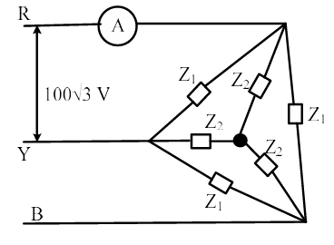
\caption{Two balanced three-phase loads for Question 34} \end{figure}
\vspace{0.3in}
SSolution
Given:
- Line voltage: \(V_L = 100\sqrt{3}\) V
- Frequency: \(f = 50\) Hz
- Load 1: \(Z_1 = 18 + j24~\Omega\) (star-connected, assumed)
- Load 2: \(Z_2 = 6 + j8~\Omega\) (delta-connected, assumed)
Step 1: Phase voltage
Step 2: Analyze Load 1 (Star-connected)
Impedance magnitude:
Phase current in Load 1:
For star connection, line current = phase current:
Step 3: Analyze Load 2 (Delta-connected)
Impedance magnitude:
For delta connection, voltage across each phase impedance = line voltage:
Phase current in Load 2:
Line current in delta connection:
Alternative interpretation - Both star-connected:
If both loads are star-connected and connected in parallel:
Load 1:
Load 2:
Total line current (if ammeter measures line current):
For parallel star loads, currents add as phasors. However, since both loads have the same power factor angle:
For \(Z_1 = 18 + j24\):
For \(Z_2 = 6 + j8\):
Since both impedances have the same angle, the currents are in phase and add directly:
Rounding to nearest integer: \(I = 13\) A
Checking if ammeter measures only one load:
If the ammeter is placed to measure only Load 2:
Answer: 10 A
\textit{Note: The exact circuit configuration from Figure Q34 would clarify whether the ammeter measures one load, total current, or a specific branch.}
QQuestion 5 2 Mark
The fuel cost functions in rupees/hour for two 600 MW thermal power plants are given by
Plant 1: \(C_1 = 350 + 6P_1 + 0.004P_1^2\)
Plant 2: \(C_2 = 450 + aP_2 + 0.003P_2^2\)
where \(P_1\) and \(P_2\) are power generated by plant 1 and plant 2, respectively, in MW and \(a\) is constant. The incremental cost of power (\(\lambda\)) is 8 rupees per MWh. The two thermal power plants together meet a total power demand of 550 MW. The optimal generation of plant 1 and plant 2 in MW, respectively, are
\vspace{0.3in}
AOptions
- 200, 350
- 250, 300
- 325, 225
- 350, 200
SSolution
Given:
- Plant 1 capacity: 600 MW
- Plant 2 capacity: 600 MW
- Cost function Plant 1: \(C_1 = 350 + 6P_1 + 0.004P_1^2\) Rs/hr
- Cost function Plant 2: \(C_2 = 450 + aP_2 + 0.003P_2^2\) Rs/hr
- Incremental cost: \(\lambda = 8\) Rs/MWh
- Total demand: \(P_1 + P_2 = 550\) MW
Step 1: Incremental cost (IC) equations
The incremental cost is the derivative of the cost function:
For Plant 1:
For Plant 2:
Step 2: Optimal dispatch condition
For economic dispatch, the incremental costs must be equal to the system lambda:
From Plant 1:
Step 3: Calculate \(P_2\)
From total demand:
Step 4: Verify with Plant 2
For consistency, let's find the value of \(a\):
Verification:
Plant 1: \(IC_1 = 6 + 0.008(250) = 6 + 2 = 8\) Rs/MWh ✓
Plant 2: \(IC_2 = 6.2 + 0.006(300) = 6.2 + 1.8 = 8\) Rs/MWh ✓
Both incremental costs equal \(\lambda = 8\) Rs/MWh, confirming optimal dispatch.
Correct answer: (B) 250, 300
QQuestion 6 2 Mark
Two generating units rated for 250 MW and 400 MW have governor speed regulations of 6% and 6.4%, respectively, from no load to full load. Both the generating units are operating in parallel to share a load of 500 MW. Assuming free governor action, the load shared in MW, by the 250 MW generating unit is \fillin[192][1in]. (round off to nearest integer)
SSolution
Given:
- Unit 1: Rating = 250 MW, Regulation = 6%
- Unit 2: Rating = 400 MW, Regulation = 6.4%
- Total load: \(P_L = 500\) MW
- Free governor action (droop characteristics)
Step 1: Understanding speed regulation
Speed regulation (R) is defined as:
For load sharing with droop characteristics:
where \(\Delta f\) is the frequency deviation and \(P\) is the load in per unit.
Step 2: Calculate droop constants
For Unit 1:
Droop constant: \(K_1 = \frac{1}{R_1 \times P_{rated,1}} = \frac{1}{0.06 \times 250}\)
For Unit 2:
Droop constant: \(K_2 = \frac{1}{R_2 \times P_{rated,2}} = \frac{1}{0.064 \times 400}\)
Step 3: Load sharing principle
For parallel operation with free governor action, the frequency drop is the same for both units:
Or equivalently:
The load sharing ratio:
Step 4: Calculate individual loads
From \(P_1 + P_2 = 500\) and \(\frac{P_1}{P_2} = \frac{2}{3}\):
Substituting:
Answer: 200 MW