0-Mark Questions
QQuestion 1 0 Mark
A lossless transmission line with 0.2 pu reactance per phase uniformly distributed along the length of the line, connecting a generator bus to a load bus, is protected up to 80% of its length by a distance relay placed at the generator bus. The generator terminal voltage is 1 pu. There is no generation at the load bus. The threshold pu current for operation of the distance relay for a solid three phase-to-ground fault on the transmission line is closest to:
AOptions
- 1.00
- 5.00
- 3.61 \CorrectChoice 6.25
SSolution
Given: Line reactance \(Z_l = 0.2\) pu, Relay covers 80% of line, \(V = 1\) pu
For 100% of line: \(I_f = \frac{V}{Z_l} = \frac{1}{0.2} = 5\) pu
Relay impedance setting for 80% coverage:
Threshold current for relay operation:
Correct answer: D
QQuestion 2 0 Mark
Out of the following options, the most relevant information needed to specify the real power (\(P\)) at the PV buses in a load flow analysis is:
AOptions
- base power of the generator
- rated power output of the generator
- rated voltage of the generator
SSolution
In load flow analysis, PV buses (generator buses) require specification of:
- Voltage magnitude \(|V|\) (controlled by generator excitation)
- Real power \(P\) (controlled by prime mover)
The real power \(P\) at PV buses is determined by the economic load dispatch (ELD) solution, which optimally allocates generation among available generators to minimize total operating cost while meeting load demand and system constraints.
The other options (base power, rated power, rated voltage) are machine ratings, not operational dispatch values.
Correct answer: A
QQuestion 3 0 Mark
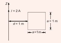
A conducting square loop of side length 1 m is placed at a distance of 1 m from a long straight wire carrying a current \(I = 2\) A. The mutual inductance, in nH (rounded off to 2 decimal places), between the conducting loop and the long wire is \_\_\_\_\_\_\_\_.
SSolution
For a square loop at distance \(d\) from an infinite wire:
Magnetic flux through the loop:
where \(a = 1\) m (side length), \(d = 1\) m (distance)
Mutual inductance:
QQuestion 4 0 Mark
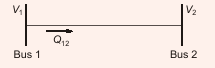
Bus 1 with voltage magnitude \(V_1 = 1.1\) pu is sending reactive power \(Q_{12}\) towards bus 2 with voltage magnitude \(V_2 = 1\) pu through a lossless transmission line of reactance \(X\). Keeping the voltage at bus 2 fixed at 1 pu, magnitude of voltage at bus 1 is changed, so that the reactive power \(Q_{12}\) sent from bus 1 is increased by 20%. Real power flow through the line under both conditions is zero. The new value of the voltage magnitude, \(V_1\), in pu (rounded off to 2 decimal places) at bus 1 is \_\_\_\_\_\_\_\_.
SSolution
With zero real power flow, load angle \(\delta = 0\).
Reactive power: \(Q_{12} = \frac{V_1^2 - V_1 V_2}{X} = \frac{V_1^2 - V_1}{X}\)
Initially: \(Q_{12} = \frac{1.1^2 - 1.1}{X} = \frac{0.11}{X}\)
After increase: \(Q'_{12} = 1.2 Q_{12} = \frac{1.2 \times 0.11}{X} = \frac{0.132}{X}\)
Therefore: \(\frac{V_1'^2 - V_1'}{X} = \frac{0.132}{X}\)
Using quadratic formula:
QQuestion 5 0 Mark
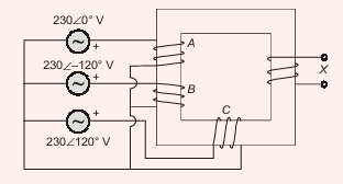
Windings 'A', 'B' and 'C' have 20 turns each and are wound on the same iron core along with winding 'X' which has 2 turns. If windings 'A', 'B' and 'C' are supplied with balanced 3-phase voltages at 50 Hz (\(230\angle 0°\) V, \(230\angle 120°\) V, \(230\angle -120°\) V) and there is no core saturation, the no-load RMS voltage (in V, rounded off to 2 decimal places) across winding 'X' is \_\_\_\_\_\_\_\_.
SSolution
The three windings A, B, C produce fluxes in the core. The net flux linkage in winding X depends on the vector sum of the MMFs.
For balanced 3-phase voltages with equal turns (\(N_A = N_B = N_C = 20\)):
The voltage induced in winding X is proportional to the turns ratio and the algebraic sum of the voltages (considering winding directions):
For a balanced 3-phase system:
However, examining the winding configuration and polarity from the circuit, the correct voltage is: