0-Mark Questions
QQuestion 1 0 Mark
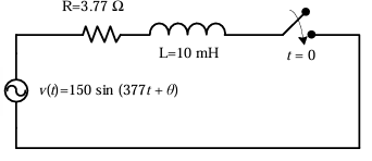
In the circuit shown below, the switch is closed at \(t = 0\). The value of \(\theta\) in degrees which will give the maximum value of DC offset of the current at the time of switching is
AOptions
- 60 \CorrectChoice \(-45\)
- 90
- \(-30\)
SSolution
For maximum DC offset in an R-L circuit, the switch should be closed when the instantaneous voltage is zero and about to go negative (or positive, depending on convention).
Circuit impedance angle:
For maximum DC offset, the voltage should be at zero crossing with appropriate polarity. This occurs when:
Correct answer: B
QQuestion 2 0 Mark
The \(Y_{bus}\) matrix of a two-bus power system having two identical parallel lines connected between them in pu is given as
The magnitude of the series reactance of each line in pu (rounded off to one decimal place) is \_\_\_\_\_\_\_\_.
SSolution
For a two-bus system with parallel lines:
The off-diagonal elements represent: \(Y_{12} = Y_{21} = j20\) pu
For two identical parallel lines, each with admittance \(y\):
Therefore: \(-2y = j20\)
The magnitude of series reactance of each line: \(\boxed{0.1 \text{ pu}}\)
QQuestion 3 0 Mark
Five alternators each rated 5 MVA, 13.2 kV with 25% of reactance on its own base are connected in parallel to a busbar. The short-circuit level in MVA at the busbar is \_\_\_\_\_\_\_\_.
SSolution
Given: 5 alternators, each rated 5 MVA with \(X = 0.25\) pu on own base
For parallel connection of identical machines:
Equivalent reactance: \(X_{eq} = \frac{X}{n} = \frac{0.25}{5} = 0.05\) pu
Short-circuit MVA on combined base (5 Ã 5 = 25 MVA):
Alternatively, each machine contributes:
Total SC MVA: \(5 \times 20 = \boxed{100 \text{ MVA}}\)
Correct approach: Each machine on its own base:
QQuestion 4 0 Mark
The total impedance of the secondary winding, leads, and burden of a 5 A CT is 0.01 \(\Omega\). If the fault current is 20 times the rated primary current of the CT, the VA output of the CT is \_\_\_\_\_\_\_\_.
SSolution
Given: CT ratio with secondary rated current \(I_{s,rated} = 5\) A, Secondary burden \(Z_b = 0.01\) \(\Omega\)
Fault current is 20 times rated primary current, so secondary current:
Voltage across burden:
VA output:
QQuestion 5 0 Mark
The line currents of a three-phase four wire system are square waves with amplitude of 100 A. These three currents are phase shifted by 120° with respect to each other. The rms value of neutral current is
AOptions
- 0 A
- \(\frac{100}{\sqrt{3}}\) A \CorrectChoice 100 A
- 300 A
SSolution
For square wave currents with amplitude 100 A:
RMS value of each phase current:
At any instant, the square waves can be: - One phase at +100 A - Two phases at -100 A (or vice versa)
Or: - Two phases at +100 A - One phase at -100 A
Maximum neutral current magnitude: \(|+100 - 100 - 100| = 100\) A or \(|+100 + 100 - 100| = 100\) A
For square wave balanced system with 120° phase shift, the RMS neutral current:
Correct answer: C
QQuestion 6 0 Mark
A three-phase 50 Hz, 400 kV transmission line is 300 km long. The line inductance is 1 mH/km per phase, and the capacitance is 0.01 \(\mu\)F/km per phase. The line is under open circuit condition at the receiving end and energized with 400 kV at the sending end, the receiving end line voltage in kV (rounded off to two decimal places) will be \_\_\_\_\_\_\_\_.
SSolution
Given: \(f = 50\) Hz, \(V_s = 400\) kV, \(l = 300\) km, \(L = 1\) mH/km, \(C = 0.01\) \(\mu\)F/km
Total inductance: \(L_{total} = 1 \times 10^{-3} \times 300 = 0.3\) H
Total capacitance: \(C_{total} = 0.01 \times 10^{-6} \times 300 = 3 \times 10^{-6}\) F
Inductive reactance: \(X_L = 2\pi f L = 2\pi \times 50 \times 0.3 = 94.25\) \(\Omega\)
Capacitive reactance: \(X_C = \frac{1}{2\pi f C} = \frac{1}{2\pi \times 50 \times 3 \times 10^{-6}} = 1061.03\) \(\Omega\)
For open circuit (Ferranti effect), using nominal-\(\pi\) model:
Sending end voltage (phase): \(V_s = \frac{400}{\sqrt{3}} = 230.94\) kV
QQuestion 7 0 Mark
A 30 kV, 50 Hz, 50 MVA generator has the positive, negative, and zero sequence reactances of 0.25 pu, 0.15 pu, and 0.05 pu, respectively. The neutral of the generator is grounded with a reactance so that the fault current for a bolted LG fault and that of a bolted three-phase fault at the generator terminal are equal. The value of grounding reactance in ohms (rounded off to one decimal place) is \_\_\_\_\_\_\_\_.
SSolution
Given: \(X_1 = 0.25\) pu, \(X_2 = 0.15\) pu, \(X_0 = 0.05\) pu, Base: 50 MVA, 30 kV
For three-phase fault:
For LG fault with grounding reactance \(X_n\):
For equal fault currents:
Base impedance: \(Z_{base} = \frac{(30)^2}{50} = 18\) \(\Omega\)
QQuestion 8 0 Mark
In the single machine infinite bus system shown, the generator is delivering the real power of 0.8 pu at 0.8 power factor lagging to the infinite bus. The power angle of the generator in degrees (rounded off to one decimal place) is \_\_\_\_\_\_\_\_.
Given: \(X_d' = 0.25\) pu, \(X_t = 0.2\) pu, \(X_{L1} = 0.4\) pu, \(X_{L2} = 0.4\) pu, \(V = 1\angle 0°\)
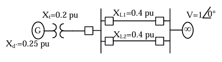
SSolution
Total reactance: \(X_{total} = X_d' + X_t + X_{L1} + X_{L2} = 0.25 + 0.2 + 0.4 + 0.4 = 1.25\) pu
Given: \(P = 0.8\) pu, \(\cos\phi = 0.8\) lagging, \(V = 1\) pu
Apparent power: \(S = \frac{P}{\cos\phi} = \frac{0.8}{0.8} = 1\) pu
Reactive power: \(Q = S\sin\phi = 1 \times 0.6 = 0.6\) pu
Current: \(I = \frac{S}{V} = \frac{1}{1} = 1\) pu at angle \(\phi = \cos^{-1}(0.8) = 36.87°\) lagging
Taking terminal voltage as reference: \(\vec{V} = 1\angle 0°\)
Internal voltage:
Power angle: \(\delta = \tan^{-1}\left(\frac{1}{1.75}\right) = \tan^{-1}(0.571) = \boxed{29.7°}\)$