1-Mark Questions
QQuestion 1 1 Mark
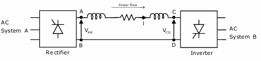
Power is transferred from system A to system B by an HVDC link as shown in the figure. If the voltages \(V_{AB}\) and \(V_{CD}\) are as indicated in the figure, and \(I > 0\), then
AOptions
- \(V_{AB} < 0, V_{CD} < 0, V_{AB} > V_{CD}\)
- \(V_{AB} > 0, V_{CD} > 0, V_{AB} > V_{CD}\)
- \(V_{AB} > 0, V_{CD} > 0, V_{AB} < V_{CD}\)
- \(V_{AB} > 0, V_{CD} < 0\)
SSolution
HVDC link operation:
Power flow direction: System A \(\rightarrow\) System B
At Rectifier (System A):
- Converts AC to DC
- DC voltage \(V_{AB}\) is positive
- Acts as source of DC power
- \(V_{AB} > 0\)
At Inverter (System B):
- Converts DC to AC
- Acts as load for DC system
- For power transfer: acts like a voltage source opposing current
- \(V_{CD} > 0\) but \(V_{CD} < V_{AB}\)
Power transfer condition:
For DC current \(I > 0\) to flow from A to B:
The voltage drop in the line is:
Both voltages are positive, but rectifier voltage must exceed inverter voltage.
Correct answer: B
QQuestion 2 1 Mark
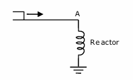
Consider a step voltage wave of magnitude 1 pu travelling along a lossless transmission line that terminates in a reactor. The voltage magnitude across the reactor at the instant the travelling wave reaches the reactor is
AOptions
- \(-1\) pu
- 1 pu
- 2 pu
- 3 pu
SSolution
Travelling wave on transmission line:
Incident wave: \(V_i = 1\) pu
Termination: Pure reactor (inductive)
Reflection coefficient:
For a reactor (inductive termination):
where \(Z_L = j\omega L\) (reactor) and \(Z_0\) is characteristic impedance.
At the instant wave arrives (very high frequency):
Reflected wave:
Total voltage at reactor:
The reactor acts like an open circuit to the fast-rising wavefront, so voltage doubles (similar to open-circuit termination).
Correct answer: C
QQuestion 3 1 Mark
Consider two buses connected by an impedance of \((0 + j5)\) \(\Omega\). The bus 1 voltage is \(100\angle 30°\) V, and bus 2 voltage is \(100\angle 0°\) V. The real and reactive power supplied by bus 1, respectively, are
AOptions
- 1000 W, 268 VAr
- \(-1000\) W, \(-134\) VAr
- 276.9 W, \(-56.7\) VAr
- \(-276.9\) W, 56.7 VAr
SSolution
Given:
- \(V_1 = 100\angle 30°\) V
- \(V_2 = 100\angle 0°\) V
- \(Z = j5\) \(\Omega\)
Current from bus 1 to bus 2:
Multiply by \(-j\):
Complex power from bus 1:
Alternatively, using direct formula:
Correct answer: A
QQuestion 4 1 Mark
A three-phase, 33 kV oil circuit breaker is rated 1200 A, 2000 MVA, 3 s. The symmetrical breaking current is
AOptions
- 1200 A
- 3600 A
- 35 kA
- 104.8 kA
SSolution
Given:
- Voltage rating: 33 kV (line-to-line)
- Current rating: 1200 A
- Breaking capacity: 2000 MVA
- Operating time: 3 s
Symmetrical breaking current:
The breaking capacity relates to the fault level the breaker can interrupt:
The symmetrical breaking current is the RMS value of the fault current that the breaker can interrupt.
Correct answer: C
QQuestion 5 1 Mark
Consider a stator winding of an alternator with an internal high-resistance ground fault. The currents under the fault condition are as shown in the figure. The winding is protected using a differential current scheme with current transformers of ratio 400/5 A as shown. The current through the operating coil is
AOptions
- 0.17875 A
- 0.2 A
- 0.375 A
- 60 A
SSolution
Given:
- CT ratio: 400/5 A
- Line currents: 220 A and 250 A (from figure)
CT secondary currents:
Current from CT1:
Current from CT2:
Differential current (through operating coil):
Under normal conditions, these would be equal. During internal fault:
This differential current indicates internal fault and operates the relay.
Correct answer: C
QQuestion 6 1 Mark
The zero-sequence circuit of the three-phase transformer shown in the figure is
(Star-Delta transformer connection shown)
SSolution
Zero-sequence behavior:
For a Star-Delta transformer:
Primary (Star side):
- Zero-sequence currents need return path through neutral
- If neutral is grounded: zero-sequence can flow
- If neutral is isolated: zero-sequence is blocked
Secondary (Delta side):
- Zero-sequence currents circulate within delta
- No zero-sequence current in lines
- Delta provides path for zero-sequence
Zero-sequence equivalent:
Primary side: Open circuit (if neutral not grounded) or through impedance (if grounded) Secondary side: Open circuit to external system (zero-sequence trapped in delta)
The zero-sequence impedance is effectively infinite from line terminals because:
- Delta blocks zero-sequence from appearing in lines
- Star side without ground also blocks zero-sequence
Correct answer: Check figure options for open circuit representation
2-Mark Questions
QQuestion 7 2 Mark
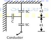
Consider a three-phase, 50 Hz, 11 kV distribution system. Each of the conductors is suspended by an insulator string having two identical porcelain insulators. The self capacitance of the insulator is 5 times the shunt capacitance between the link and the ground, as shown in the figure. The voltage across the two insulators is
AOptions
- \(e_1 = 3.74\) kV, \(e_2 = 2.61\) kV
- \(e_1 = 3.46\) kV, \(e_2 = 2.89\) kV
- \(e_1 = 6.0\) kV, \(e_2 = 4.23\) kV
- \(e_1 = 5.5\) kV, \(e_2 = 5.5\) kV
SSolution
Given:
- Line voltage: 11 kV (line-to-line)
- Self capacitance: \(C_s = 5C\) (where \(C\) is shunt capacitance)
- Two insulators in string
Phase voltage:
Voltage distribution:
Let \(e_1\) = voltage across lower insulator (nearest conductor) Let \(e_2\) = voltage across upper insulator
Using current balance at junction:
where: - \(i_1\) = current through \(C_s\) (self capacitance of lower insulator) - \(i_2\) = current through \(C_s\) (self capacitance of upper insulator) - \(i_3\) = current through \(C\) (shunt capacitance to ground from junction)
Also: \(e_1 + e_2 = 6.35\) kV
Closest to option A.
Correct answer: A
QQuestion 8 2 Mark
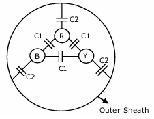
Consider a three-core, three-phase, 50 Hz, 11 kV cable whose conductors are denoted as R, Y and B in the figure. The inter-phase capacitance (\(C_1\)) between each pair of conductors is 0.2 \(\mu\)F and the capacitance between each line conductor and the sheath is 0.4 \(\mu\)F. The per-phase charging current is
AOptions
- 2.0 A
- 2.4 A
- 2.7 A
- 3.5 A
SSolution
Given:
- Line voltage: 11 kV (line-to-line)
- \(C_1 = 0.2\) \(\mu\)F (inter-phase)
- \(C_2 = 0.4\) \(\mu\)F (line-to-sheath)
- Frequency: 50 Hz
Effective capacitance per phase:
For three-phase cable, effective capacitance to neutral:
Phase voltage:
Charging current per phase:
Correct answer: A
QQuestion 9 2 Mark
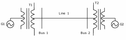
For the power system shown in the figure below, the specifications of the components are: G1: 25 kV, 100 MVA, X=9%; G2: 25 kV, 100 MVA, X=9%; T1: 25 kV/220 kV, 90 MVA, X=12%; T2: 220 kV/25 kV, 90 MVA, X=12%; Line1: 220 kV, X= 150 ohms. Choose 25 kV as the base voltage at generator G1, and 200 MVA as the MVA base. The impedance diagram is
SSolution
Base values:
- \(S_{base} = 200\) MVA (new base)
- \(V_{base,G1} = 25\) kV
Converting to new base:
Generator G1:
Generator G2: Same rating as G1:
Transformer T1:
Transformer T2: Same as T1:
Transmission Line:
Base impedance at 220 kV:
Line reactance:
Impedance diagram: - G1: j0.18 - T1: j0.27 - Line: j0.62 - T2: j0.27 - G2: j0.18
Correct answer: C