1-Mark Questions
QQuestion 1 1 Mark
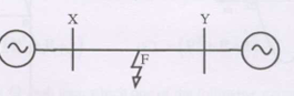
A two machine power system has a transmission line XY with positive sequence impedance \(Z_1\) and zero sequence impedance \(Z_0\). An 'a' phase to ground fault with zero fault impedance occurs at the centre of the transmission line. Bus voltage at X and line current from X to F for phase 'a' are \(V_a\) and \(I_a\). The impedance measured by the ground distance relay located at terminal X will be
AOptions
- \(Z_1/2\) \(\Omega\)
- \(Z_0/2\) \(\Omega\)
- \((Z_0 + Z_1)/2\) \(\Omega\)
- \(V_a/I_a\) \(\Omega\)
SSolution
Distance relay measurement:
The distance relay measures:
For single line-to-ground fault:
Using symmetrical components:
For SLG fault with zero impedance at mid-point:
Voltage at relay location:
Since \(I_1 = I_2 = I_0 = I_f\):
Line current:
For SLG fault:
The relay sees:
This simplifies to show the relay measures the actual distance to fault accounting for zero sequence.
Correct answer: D (\(V_a/I_a\))
QQuestion 2 1 Mark
An extra high voltage transmission line of length 300 km can be approximated by a lossless line having propagation constant \(\beta = 0.00127\) radians per km. The percentage ratio of line length to wavelength will be
AOptions
- 24.24%
- 12.12%
- 19.05%
- 6.06%
SSolution
Wavelength calculation:
Percentage ratio:
Correct answer: D
QQuestion 3 1 Mark
A 3-phase transmission line has voltage drops given by the equation with positive sequence impedance 15 \(\Omega\) and zero sequence impedance 48 \(\Omega\). The values of \(Z_s\) and \(Z_m\) will be
AOptions
- \(Z_s = 31.5\) \(\Omega\); \(Z_m = 16.5\) \(\Omega\)
- \(Z_s = 26\) \(\Omega\); \(Z_m = 11\) \(\Omega\)
- \(Z_s = 16.5\) \(\Omega\); \(Z_m = 31.5\) \(\Omega\)
- \(Z_s = 11\) \(\Omega\); \(Z_m = 26\) \(\Omega\)
SSolution
Sequence impedance relationships:
Solving simultaneously:
From first equation: \(Z_s = Z_1 + Z_m = 15 + Z_m\)
Substitute in second:
Correct answer: B
2-Mark Questions
QQuestion 4 2 Mark
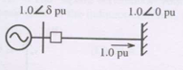
Voltage phasors at two terminals of a 70 km transmission line have magnitude 1.0 pu but are 180° out of phase. Maximum load current is 1/5th of minimum 3-phase fault current. Which protection scheme will NOT pick up?
AOptions
- Distance protection using mho relays with zone-1 set to 80% of line impedance
- Directional overcurrent protection set to pick up at 1.25 times maximum load current
- Pilot relaying with directional comparison
- Pilot relaying with segregated phase comparison
SSolution
Condition analysis:
Voltages 180° out of phase with equal magnitude indicates the system is at stability limit or beyond.
This is an unusual operating condition (system collapse).
Current magnitude:
With maximum load current = (1/5) Ã minimum fault current, and voltages at 180°, the current will be relatively low.
Protection scheme analysis:
(A) Mho relay: Impedance-based, will operate based on V/I ratio
(B) Directional overcurrent: Set at 1.25 Ã \(I_{max,load}\) - Current at 180° condition may not exceed this setting - May NOT pick up if current is below setting
(C) Directional comparison: Compares direction at both ends, will detect
(D) Phase comparison: Compares phase angles, will detect
Correct answer: B
QQuestion 5 2 Mark
A lossless transmission line having Surge Impedance Loading (SIL) of 2280 MW is provided with uniformly distributed series capacitive compensation of 30%. The SIL of the compensated line will be
AOptions
- 1835 MW
- 2280 MW
- 2725 MW
- 3257 MW
SSolution
SIL definition:
where \(Z_c = \sqrt{L/C}\) is characteristic impedance.
With series capacitive compensation:
Effective inductance: \(L_{eff} = L(1 - k)\) where \(k = 0.3\)
New SIL:
Correct answer: C
QQuestion 6 2 Mark
A lossless power system serves 250 MW load. Two generators with cost curves \(C_1(P_{G1}) = P_{G1} + 0.055P_{G1}^2\) and \(C_2(P_{G2}) = 3P_{G2} + 0.03P_{G2}^2\). The minimum cost dispatch will be
AOptions
- \(P_{G1} = 250\) MW; \(P_{G2} = 0\) MW
- \(P_{G1} = 150\) MW; \(P_{G2} = 100\) MW
- \(P_{G1} = 100\) MW; \(P_{G2} = 150\) MW
- \(P_{G1} = 0\) MW; \(P_{G2} = 250\) MW
SSolution
Economic dispatch condition:
Equal incremental costs:
Load constraint:
From first equation:
Substitute \(P_{G2} = 250 - P_{G1}\):
Correct answer: C
QQuestion 7 2 Mark
A lossless single machine infinite bus system: synchronous generator transfers 1.0 pu power to infinite bus. Critical clearing time is 0.28 s. If identical generator connected in parallel and each supplies 0.5 pu, the critical clearing time will
AOptions
- reduce to 0.14 s
- reduce but will be more than 0.14 s
- remain constant at 0.28 s
- increase beyond 0.28 s
SSolution
Critical clearing time dependency:
Equal area criterion:
where \(H\) is inertia constant.
Original system: - Single generator: inertia \(H_1\), power \(P_1 = 1.0\) pu - \(t_{cr,1} = 0.28\) s
New system: - Two identical generators in parallel - Total inertia: \(H_{total} = 2H_1\) - Each generator: power \(P = 0.5\) pu - Total power: still 1.0 pu to infinite bus
Effect on critical clearing time:
The system inertia doubles, which increases the critical clearing time:
The critical clearing time increases because the combined system has more inertia.
Correct answer: D
QQuestion 8 2 Mark
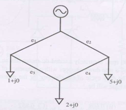
Single line diagram of 4-bus distribution system with branches \(e_1, e_2, e_3, e_4\) having equal impedances. Load currents shown in per unit. Company policy requires radial operation with minimum loss. This can be achieved by opening branch
SSolution
Minimum loss in radial distribution:
For minimum loss, open the branch that carries minimum current.
Analysis:
With equal impedances, loss in each branch: \(I^2R\)
Total loss is minimized by opening the branch with minimum current flow.
Need to calculate current distribution for each possible radial configuration by opening one branch at a time.
Without the specific network diagram and load positions, the general principle is:
- Calculate current in each branch
- Open branch with minimum current
- This minimizes \(\sum I^2R\)
Answer depends on specific network topology shown in figure