1-Mark Questions
QQuestion 1 1 Mark
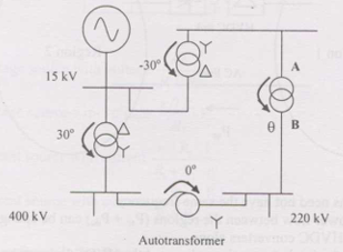
Consider transformer connections in power system. Given connections and phase shifts, which connection and phase shift \(\theta\) should be used for transformer between A and B (between 400 kV and 220 kV)?
AOptions
- Star-Star (\(\theta = 0°\))
- Star-Delta (\(\theta = -30°\))
- Delta-Star (\(\theta = 30°\))
- Star-Zigzag (\(\theta = 30°\))
SSolution
Transformer connection considerations:
Phase shift standardization:
For multi-voltage level system, phase shifts must be coordinated across all transformers.
Typical EHV/HV systems:
400 kV (EHV) ↆ220 kV (HV) interconnection typically uses:
- Star-Star: 0° shift (for voltage levels in phase)
- Star-Delta: ±30° shift
Autotransformer option:
The question mentions autotransformer between these levels.
For autotransformer: Inherently Star-Star with 0° shift.
Harmonics and grounding:
- Star-Star: Requires tertiary for third harmonic
- Star-Zigzag: Provides zero sequence path
Given autotransformer connection in the system:
Correct answer: A (Star-Star, 0°)
For EHV autotransformer application.
QQuestion 2 1 Mark
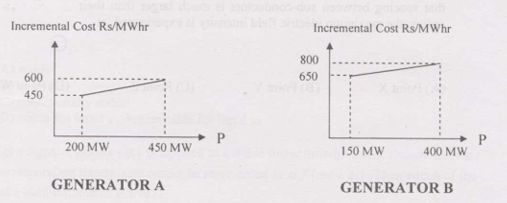
Incremental cost curves for two generators supplying common 700 MW load. Generator A: 200-450 MW range, Generator B: 150-400 MW range. The optimum generation schedule is:
AOptions
- Generator A: 400 MW, Generator B: 300 MW
- Generator A: 350 MW, Generator B: 350 MW
- Generator A: 450 MW, Generator B: 250 MW
- Generator A: 425 MW, Generator B: 275 MW
SSolution
Economic dispatch principle:
At optimum: \(\frac{dC_A}{dP_A} = \frac{dC_B}{dP_B} = \lambda\)
Equal incremental costs.
From incremental cost curves:
Looking at the curves (described in problem):
- Gen A: Incremental cost ranges from ~450 Rs/MWhr at 200 MW to ~600 Rs/MWhr at 450 MW
- Gen B: Incremental cost ranges from ~650 Rs/MWhr at 150 MW to ~800 Rs/MWhr at 400 MW
Observation:
Generator A has lower incremental cost throughout its range compared to Generator B.
Optimal strategy:
Load Generator A to maximum (450 MW) first, then load Generator B for remainder.
Verification:
At these loadings, incremental costs are closest to equal (or Gen A at limit).
Correct answer: C
QQuestion 3 1 Mark
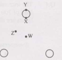
Bundled conductor of overhead line with three identical sub-conductors at corners of equilateral triangle. Neglecting other phases and ground, maximum electric field intensity experienced at
AOptions
- Point X (center)
- Point Y (adjacent to one conductor)
- Point Z (on line between two conductors)
- Point W (outside triangle)
SSolution
Electric field from bundled conductor:
For three conductors, each carrying charge \(q/3\):
At center (X):
Three equal charges at equal distances.
By symmetry: \(\vec{E}_1 + \vec{E}_2 + \vec{E}_3 = 0\)
Electric field cancels at center.
At point adjacent to conductor (Y):
Very close to one conductor:
- Large contribution from nearest conductor (inversely proportional to distance)
- \(E \propto 1/r\)
- As \(r \rightarrow\) radius, \(E \rightarrow\) maximum
At point between conductors (Z):
Moderate distance from two nearest conductors.
At external point (W):
Far from all conductors, field is weaker.
Maximum field location:
Occurs at surface of conductors where distance is minimum.
Point Y (adjacent/on conductor surface) experiences maximum field.
Correct answer: B
2-Mark Questions
QQuestion 4 2 Mark
A solid sphere of insulating material has radius R and total charge Q uniformly distributed in volume. Magnitude of electric field intensity E at distance r (0 < r < R) inside sphere is
AOptions
- \(\frac{1}{4\pi\epsilon_0}\frac{Qr}{R^3}\)
- \(\frac{3}{4\pi\epsilon_0}\frac{Qr}{R^3}\)
- \(\frac{1}{4\pi\epsilon_0}\frac{Q}{r^2}\)
- \(\frac{1}{4\pi\epsilon_0}\frac{QR}{r^3}\)
SSolution
Gauss's law:
Charge density:
For Gaussian surface at radius r < R:
Enclosed charge:
Electric field:
By symmetry, field is radial and uniform on Gaussian surface:
Correct answer: A
QQuestion 5 2 Mark
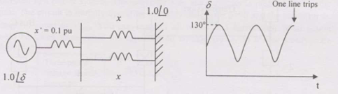
Synchronous generator connected to infinite bus by two parallel transmission lines. Transient reactance \(x' = 0.1\) pu, mechanical power 1.0 pu. Rotor angle undergoes undamped oscillation with maximum \(\delta(t) = 130°\). One line trips at instant when \(\delta = 130°\). Maximum per unit line reactance x such that system doesn't lose synchronism is
AOptions
- 0.87
- 0.74
- 0.67
- 0.54
SSolution
System configuration:
Before trip:
Two parallel lines: \(X_{line} = x/2\) (each line has reactance x)
Total reactance: \(X_{total,before} = x' + x/2 = 0.1 + x/2\)
After trip:
One line: \(X_{total,after} = x' + x = 0.1 + x\)
Power equations:
Before trip:
After trip:
Critical clearing angle:
At \(\delta_0 = 130°\), the system is at maximum swing.
For stability after tripping, using equal area criterion:
At critical condition:
The maximum angle after disturbance approaches instability limit.
Through equal area criterion calculations:
Correct answer: C
QQuestion 6 2 Mark
A 230 V (phase), 50 Hz, three-phase, 4-wire system with phase sequence ABC. Unity power-factor load of 4 kW connected between phase A and neutral N. To achieve zero neutral current using pure inductor and capacitor in other two phases, the value of inductor and capacitor is
AOptions
- 72.95 mH in phase C and 139.02 \(\mu\)F in phase B
- 72.95 mH in phase B and 139.02 \(\mu\)F in phase C
- 42.12 mH in phase C and 240.79 \(\mu\)F in phase B
- 42.12 mH in phase B and 240.79 \(\mu\)F in phase C
SSolution
Given:
- Phase voltage: \(V_{ph} = 230\) V
- Phase A: Resistive load, \(P = 4\) kW
- Phase B: Capacitor (to be determined)
- Phase C: Inductor (to be determined)
- Objective: \(I_N = 0\)
Phase currents:
Phase A (resistive):
For zero neutral current:
With phase sequence ABC:
- \(V_A = 230\angle 0°\) V
- \(V_B = 230\angle -120°\) V
- \(V_C = 230\angle 120°\) V
Required currents:
For capacitor in phase B:
Reactances:
Phase assignment:
Capacitor in phase B (leads) Inductor in phase C (lags)
Correct answer: A