1-Mark Questions
QQuestion 1 1 Mark
If the following switching devices have similar power ratings, which one of them is the fastest?
AOptions
- SCR
- GTO
- IGBT
- Power MOSFET
SSolution
Comparison of Power Semiconductor Devices:
1. SCR (Silicon Controlled Rectifier / Thyristor):
- Turn-ON: Relatively fast (few microseconds)
- Turn-OFF: Very slow (requires external commutation circuit)
- Turn-off time: 50-100 μs (typical)
- Cannot be turned off by gate signal
- Suitable for line-frequency applications (50/60 Hz)
- Switching frequency: Up to few kHz
2. GTO (Gate Turn-Off Thyristor):
- Turn-ON: Fast (few microseconds)
- Turn-OFF: Can be turned off by negative gate pulse
- Turn-off time: 10-20 μs (typical)
- Requires large negative gate current for turn-off
- Switching frequency: Up to 5-10 kHz
- Slower than MOSFET and IGBT
3. IGBT (Insulated Gate Bipolar Transistor):
- Turn-ON: Fast (100-500 ns)
- Turn-OFF: Fast (200-1000 ns)
- Voltage-controlled device (like MOSFET)
- Low gate drive power
- Switching frequency: 20-50 kHz (modern IGBTs up to 100 kHz)
- Combines advantages of MOSFET and BJT
- Fast, but not as fast as MOSFET
4. Power MOSFET (Metal-Oxide-Semiconductor Field-Effect Transistor):
- Turn-ON: Very fast (10-100 ns)
- Turn-OFF: Very fast (10-100 ns)
- Voltage-controlled device
- Very low gate drive power
- Switching frequency: 100 kHz to several MHz
- Fastest switching among all four devices
- No minority carrier storage delay
- Limited to lower voltage and power ratings compared to IGBT and GTO
Speed Comparison (Turn-off time):
- SCR: 50-100 μs (slowest)
- GTO: 10-20 μs
- IGBT: 0.2-1 μs
- Power MOSFET: 10-100 ns (fastest)
Switching Frequency Capability:
- SCR: < 1 kHz
- GTO: 5-10 kHz
- IGBT: 20-100 kHz
- Power MOSFET: 100 kHz - MHz
Why MOSFET is Fastest:
- Unipolar device: Only majority carriers (electrons) participate
- No minority carrier storage: No storage delay during turn-off
- Fast gate response: High input impedance, charges/discharges quickly
- Voltage-controlled: No base current required
- Low switching losses: Due to fast switching times
Trade-offs:
- MOSFETs: Fastest but limited voltage/current ratings
- IGBTs: Good speed with higher power capability
- GTOs: Moderate speed but very high power
- SCRs: Slowest but highest power and simplest
Correct answer: D (Power MOSFET)
\textit{Note: While power MOSFETs are the fastest, IGBTs are preferred for medium to high power applications due to better power handling capability. The choice depends on the application requirements of speed versus power rating.}
QQuestion 2 1 Mark
A single-phase triac based AC voltage controller feeds a series RL load. The input AC supply is 230 V, 50 Hz. The values of R and L are 10 \(\Omega\) and 18.37 mH, respectively. The minimum triggering angle of the triac to obtain controllable output voltage is
AOptions
- 15°
- 30°
- 45°
- 60°
SSolution
Given:
- Supply voltage: \(V = 230\) V (RMS), 50 Hz
- Load resistance: \(R = 10\) \(\Omega\)
- Load inductance: \(L = 18.37\) mH \(= 0.01837\) H
- AC voltage controller with Triac
- Find: Minimum triggering angle for controllable output
Solution:
Step 1: Understanding AC voltage controller with RL load
For an RL load, the load current lags the voltage by phase angle \(\phi\).
The impedance angle is:
where \(X_L = \omega L = 2\pi f L\)
Step 2: Calculate inductive reactance
Step 3: Calculate load impedance angle
Step 4: Minimum firing angle for controllable output
For an AC voltage controller with RL load:
Key Concept: When the triac is triggered at angle \(\alpha\), current starts flowing. However, due to the inductive load, current cannot change instantaneously and continues to flow even after the voltage reverses polarity.
For the triac to turn off properly and allow control:
- The current must go through zero
- This happens when the natural current zero crossing occurs
Condition for controllability:
The triac turns off when current becomes zero. For an RL load with firing angle \(\alpha\):
- Current starts at \(\alpha\)
- Current lags voltage by \(\phi\)
- Current extinction angle: \(\beta\)
For proper control (triac turns off before next half-cycle trigger):
If \(\alpha < \phi\):
- Current from previous half-cycle is still flowing
- Triac cannot turn off
- Loss of control
- Output becomes uncontrolled (like full-wave)
Minimum firing angle:
Physical Explanation:
For \(\alpha < 30°\):
- When triac is triggered at (say) \(\alpha = 15°\)
- Current starts but lags by \(30°\)
- Current peak occurs at \(15° + 90° - 30° = 75°\)
- Current zero occurs after \(180° + 15° - 30° = 165°\) (in next half cycle)
- Before this zero crossing, the opposite triac is triggered
- Both directions conduct simultaneously
- Results in continuous conduction (uncontrolled)
For \(\alpha \geq 30°\):
- Current extinguishes before next triggering
- Proper control is achieved
- Output voltage can be controlled
Mathematical Verification:
For RL load with firing angle \(\alpha\):
Current extinction angle:
For next half-cycle trigger to not overlap:
For symmetric triggering:
This is always satisfied, but for controllability:
However, the critical condition is:
Correct answer: B (30°)
\textit{Note: This is a fundamental limitation of AC voltage controllers with RL loads. The minimum firing angle must equal or exceed the load power factor angle to maintain controllability.}
QQuestion 3 1 Mark
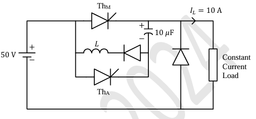
A forced commutated thyristorized step-down chopper is shown in the figure. Neglect the ON-state drop across the power devices. Assume that the capacitor is initially charged to 50 V with the polarity shown in the figure. The load current (\(I_L\)) can be assumed to be constant at 10 A. Initially, Th\(_M\) is ON and Th\(_A\) is OFF. The turn-off time available to Th\(_M\) in microseconds, when Th\(_A\) is triggered, is_________ (rounded off to the nearest integer).
SSolution
Given:
- Capacitor: \(C = 10\) μF
- Initial capacitor voltage: \(V_C = 50\) V (charged with polarity shown)
- Load current: \(I_L = 10\) A (constant)
- Supply voltage: \(V_s = 50\) V
- Initially: Th\(_M\) is ON, Th\(_A\) is OFF
- ON-state drops neglected
Circuit Operation:
Before Th\(_A\) is triggered:
- Th\(_M\) is conducting
- Load current flows through Th\(_M\)
- Capacitor is charged to 50 V with top plate positive
When Th\(_A\) is triggered (Commutation process):
- Th\(_A\) turns ON
- Capacitor voltage (50 V, negative at bottom) applies reverse bias to Th\(_M\)
- Th\(_M\) turns OFF
- Load current now flows through capacitor
- Capacitor starts discharging and then charging in opposite direction
Solution:
Step 1: Circuit analysis after Th\(_A\) triggers
When Th\(_A\) is triggered:
- Initial capacitor voltage: \(V_C(0^+) = -50\) V (across Th\(_M\), reverse bias)
- Load current charges capacitor: \(I_L = 10\) A (constant)
The capacitor voltage changes as:
Step 2: Turn-off time for Th\(_M\)
Th\(_M\) remains reverse biased as long as \(v_C(t) < 0\).
When \(v_C(t) = 0\):
After this time, capacitor voltage becomes positive, and forward bias appears across Th\(_M\).
Step 3: Available turn-off time
The turn-off time available to Th\(_M\) is:
During this time:
- Th\(_M\) is reverse biased
- Carriers recombine in Th\(_M\) junctions
- Th\(_M\) regains forward blocking capability
Verification:
Energy balance:
- Initial energy in capacitor: \(E_i = \frac{1}{2}CV_C^2 = \frac{1}{2} \times 10 \times 10^{-6} \times 50^2 = 12.5\) mJ
- Energy to bring capacitor to zero: \(E = \frac{1}{2}CV_C^2 = 12.5\) mJ
- Charge transfer: \(Q = CV_C = 10 \times 10^{-6} \times 50 = 500\) μC
- Time: \(t = \frac{Q}{I_L} = \frac{500 \times 10^{-6}}{10} = 50\) μs ✓
Circuit behavior after 50 μs:
- Capacitor voltage continues to increase positively
- Eventually reaches: \(v_C = V_s - V_{diode} \approx 50\) V (opposite polarity)
- Capacitor is now ready for next commutation cycle
Answer: 50 μs
\textit{Note: This is a classical forced commutation technique called voltage commutation or capacitor commutation. The capacitor provides reverse voltage to turn off the main thyristor. The turn-off time must be longer than the thyristor's turn-off time (typically 15-30 μs for conventional thyristors) for successful commutation.}
2-Mark Questions
QQuestion 4 2 Mark
A single-phase half-controlled bridge converter supplies an inductive load with ripple free load current. The triggering angle of the converter is 60°. The ratio of the rms value of the fundamental component of the input current to the rms value of the total input current of the bridge is _________ (rounded off to 3 decimal places).
SSolution
Given:
- Single-phase half-controlled bridge converter
- Load: Inductive with ripple-free (constant) current
- Firing angle: \(\alpha = 60°\)
- Find: \(\frac{I_{s1,rms}}{I_{s,rms}}\) (ratio of fundamental RMS to total RMS)
Solution:
Step 1: Understanding half-controlled bridge
A half-controlled bridge has:
- Two thyristors (controlled)
- Two diodes (uncontrolled)
- Configuration: T\(_1\)-T\(_2\) (thyristors), D\(_1\)-D\(_2\) (diodes)
Step 2: Input current waveform
With ripple-free load current \(I_0\) (constant):
Positive half-cycle (\(0° < \omega t < 180°\)):
- \(0° < \omega t < \alpha\): No conduction (waiting for trigger)
- \(\alpha < \omega t < 180°\): T\(_1\) and D\(_2\) conduct, \(i_s = +I_0\)
Negative half-cycle (\(180° < \omega t < 360°\)):
- \(180° < \omega t < 180° + \alpha\): Freewheeling through D\(_1\)-D\(_2\), \(i_s = 0\)
- \(180° + \alpha < \omega t < 360°\): T\(_2\) and D\(_1\) conduct, \(i_s = -I_0\)
Input current waveform:
Step 3: RMS value of total input current
With \(\alpha = 60° = \frac{\pi}{3}\) rad:
Step 4: Fundamental component using Fourier analysis
The fundamental component of the input current:
where:
For the given waveform:
Fundamental amplitude:
RMS value of fundamental:
With \(\alpha = 60°\), \(\cos 60° = 0.5\):
Step 5: Calculate ratio
Answer: 0.827
QQuestion 5 2 Mark
A single-phase full bridge voltage source inverter (VSI) feeds a purely inductive load. The inverter output voltage is a square wave in 180° conduction mode. The fundamental frequency of the output voltage is 50 Hz. If the DC input voltage of the inverter is 100 V and the value of the load inductance is 20 mH, the peak-to-peak load current in amperes is _________ (rounded off to the nearest integer).
SSolution
Given:
- Single-phase full bridge VSI
- Load: Purely inductive, \(L = 20\) mH \(= 0.02\) H
- Output voltage: Square wave, 180° conduction mode
- Fundamental frequency: \(f = 50\) Hz
- DC input voltage: \(V_{dc} = 100\) V
- Find: Peak-to-peak load current
Solution:
Step 1: Output voltage waveform
For 180° conduction mode full bridge inverter:
This is a square wave with amplitude \(\pm V_{dc} = \pm 100\) V.
Step 2: Fourier series of square wave
Fundamental component:
Step 3: Current due to fundamental component
For purely inductive load:
For sinusoidal voltage \(v_{o1}(t) = V_{o1,peak} \sin(\omega t)\):
Integrating:
For steady state with purely inductive load, average current is zero, so \(C = 0\):
Or equivalently:
Peak current due to fundamental:
Step 4: Current due to harmonics
For harmonic order \(n\) (odd harmonics: 3, 5, 7, ...):
Voltage: \(v_{on}(t) = \frac{4V_{dc}}{n\pi} \sin(n\omega t)\)
Current: \(i_n(t) = \frac{4V_{dc}}{n\pi \cdot n\omega L} \sin(n\omega t - 90°)\)
Peak current of \(n^{th}\) harmonic:
Step 5: Total peak-to-peak current
For purely inductive load with square wave voltage, we need to find the current ripple.
During positive half-cycle (\(0 < t < T/2\)):
Current increases linearly from negative peak to positive peak:
This is the peak-to-peak current.
Alternative verification:
For square wave voltage with amplitude \(V_{dc}\):
The current waveform is triangular (purely inductive load).
Peak-to-peak current:
Current waveform characteristics:
- Triangular wave (due to constant \(di/dt\))
- Zero average (purely inductive)
- Varies from \(-25\) A to \(+25\) A
- Peak-to-peak: 50 A
Answer: 50 A
\textit{Note: For a purely inductive load with square wave voltage, the current is triangular. The peak-to-peak current is determined by the volt-second area applied across the inductor during each half-cycle.}
QQuestion 6 2 Mark
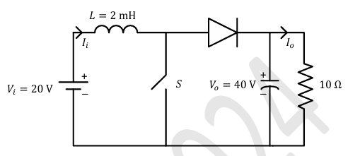
In the DC-DC converter shown in the figure, the current through the inductor is continuous. The switching frequency is 500 Hz. The voltage (\(V_o\)) across the load is assumed to be constant and ripple free. The peak inductor current in amperes is _________ (rounded off to the nearest integer).
SSolution
Given:
- DC-DC converter (Buck-Boost topology from figure)
- Inductor: \(L = 2\) mH \(= 0.002\) H
- Input voltage: \(V_i = 20\) V
- Output voltage: \(V_o = 40\) V (constant, ripple-free)
- Load resistance: \(R = 10\) \(\Omega\)
- Switching frequency: \(f_s = 500\) Hz
- Inductor current: Continuous conduction mode (CCM)
- Find: Peak inductor current
Solution:
Step 1: Identify converter type and determine duty cycle
From the circuit (Buck-Boost converter):
Voltage relationship: \(\frac{V_o}{V_i} = \frac{D}{1-D}\)
where \(D\) is the duty cycle.
\(\frac{40}{20} = \frac{D}{1-D}\)
\(2(1-D) = D\)
\(2 - 2D = D\)
\(D = \frac{2}{3}\)
Step 2: Calculate output current and power
Output current: \(I_o = \frac{V_o}{R} = \frac{40}{10} = 4 \text{ A}\)
Output power: \(P_o = \frac{V_o^2}{R} = \frac{40^2}{10} = 160 \text{ W}\)
Step 3: Calculate average inductor current
For lossless converter (assuming ideal): \(P_{in} = P_{out}\)
\(V_i \times I_i = V_o \times I_o\)
For buck-boost converter, the average inductor current is related to input current:
During ON time: Inductor connects to source, \(I_L\) flows from source During OFF time: Inductor delivers to load through diode
Average input current: \(I_{in} = \frac{P_o}{V_i} = \frac{160}{20} = 8 \text{ A}\)
For buck-boost converter: \(I_{L,avg} = \frac{I_o}{1-D} = \frac{4}{1-2/3} = \frac{4}{1/3} = 12 \text{ A}\)
Alternative approach:
The relationship between average inductor current and output current: \(I_{L,avg} = I_o \times \frac{1}{1-D}\)
\(I_{L,avg} = 4 \times \frac{1}{0.333} = 12 \text{ A}\)
Step 4: Calculate inductor current ripple
During ON time (\(DT\)), switch is closed: \(v_L = V_i\)
\(\frac{\Delta i_L}{2} = \frac{V_i \times D \times T}{2L} = \frac{V_i \times D}{2L \times f_s}\)
\(\frac{\Delta i_L}{2} = \frac{20 \times \frac{2}{3}}{2 \times 0.002 \times 500}\)
\(\frac{\Delta i_L}{2} = \frac{13.33}{2} = 6.67 \text{ A}\)
Therefore: \(\Delta i_L = 13.33 \text{ A}\)
Step 5: Calculate peak inductor current
\(I_{L,peak} = I_{L,avg} + \frac{\Delta i_L}{2}\)
\(I_{L,peak} = 12 + 6.67 = 18.67 \text{ A}\)
Rounded to nearest integer: \(I_{L,peak} = 19\) A
Verification using OFF time:
During OFF time \(((1-D)T)\), diode conducts: \(v_L = -V_o\)
\(\frac{\Delta i_L}{2} = \frac{V_o \times (1-D) \times T}{2L} = \frac{V_o \times (1-D)}{2L \times f_s}\)
\(\frac{\Delta i_L}{2} = \frac{40 \times \frac{1}{3}}{2 \times 0.002 \times 500} = \frac{13.33}{2} = 6.67 \text{ A}\) ✓
Answer: 19 A
QQuestion 7 2 Mark
A single-phase full-controlled thyristor converter bridge is used for regenerative braking of a separately excited DC motor with the following specifications:
- Rated armature voltage: 210 V
- Rated armature current: 10 A
- Rated speed: 1200 rpm
- Armature resistance: 1 \(\Omega\)
- Input to converter bridge: 240 V at 50 Hz
The armature of the DC motor is fed from the full-controlled bridge and the field current is kept constant. Assume that the motor is running at 600 rpm and the armature terminals of the motor are suitably reversed for regenerative braking. If the armature current of the motor is to be maintained at the rated value, the triggering angle of the converter bridge in degrees should be ____________ (rounded off to 2 decimal places).
SSolution
In regenerative braking with armature terminals reversed:
- Back EMF \(E = 100\) V (acting as source)
- Current \(I_a = 10\) A flows from motor to converter
- For converter to accept this current (inversion mode), it must provide negative voltage
Actually, when terminals are reversed:
- The polarity of back EMF relative to converter changes
- In regenerative mode, converter provides negative DC voltage
- The motor EMF must overcome this negative voltage plus \(I_a R_a\) drop
Correct equation: \(E = |V_{dc}| + I_a R_a\)
For inversion mode, converter output is negative: \(V_{dc} = -|V_{dc}|\)
\(|V_{dc}| = E - I_a R_a = 100 - 10 = 90 \text{ V}\)
For inversion mode (\(\alpha > 90°\)): \(V_{dc} = \frac{2V_m}{\pi} \cos\alpha = -90\)
\(\cos\alpha = \frac{-90 \times \pi}{2 \times 339.41} = \frac{-282.74}{678.82} = -0.4165\)
\(\alpha = \cos^{-1}(-0.4165) = 114.62°\)
Verification:
At \(\alpha = 114.62°\): \(V_{dc} = 216.07 \times \cos(114.62°) = 216.07 \times (-0.4165) = -90 \text{ V}\)
This negative voltage allows current to flow from motor (acting as generator) back to the AC supply through the converter operating in inversion mode.
Power flow:
- Generated EMF: \(E \times I_a = 100 \times 10 = 1000\) W
- Armature loss: \(I_a^2 R_a = 100 \times 1 = 100\) W
- Power to AC supply: \(|V_{dc}| \times I_a = 90 \times 10 = 900\) W ✓
Answer: 114.62°
\textit{Note: In regenerative braking mode, the converter operates as an inverter with firing angle greater than 90°. The back EMF of the motor drives current back into the AC supply through the converter, converting mechanical energy to electrical energy.}