0-Mark Questions
QQuestion 1 0 Mark
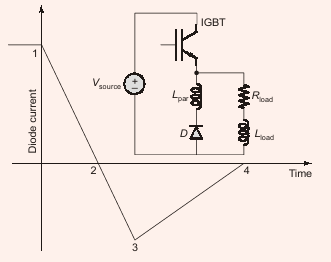
A double pulse measurement for an inductively loaded circuit controlled by an IGBT switch is carried out to evaluate the reverse recovery characteristics of the diode \(D\). The point on the diode current vs time plot (indicate choice by entering 1, 2, 3 or 4) at which the IGBT experiences the highest current stress is \_\_\_\_\_\_\_\_.
SSolution
During diode reverse recovery, the IGBT must conduct:
- The load current
- The reverse recovery current of the diode
The highest current stress occurs at point 3, which represents the peak reverse recovery current. At this instant, the IGBT conducts both the load current and the maximum reverse recovery current simultaneously.
Answer: \boxed{3}
QQuestion 2 0 Mark
A common-source amplifier with a drain resistance, \(R_D = 4.7\) k\(\Omega\), is powered using a 10 V power supply. Assuming that the transconductance, \(g_m\), is 520 \(\mu\)A/V, the voltage gain of the amplifier is closest to:
AOptions
- 1.22
- \(-1.22\)
- 2.44 \CorrectChoice \(-2.44\)
SSolution
For a common-source amplifier, the voltage gain is:
Given: \(g_m = 520\) \(\mu\)A/V \(= 520 \times 10^{-6}\) A/V, \(R_D = 4.7\) k\(\Omega = 4700\) \(\Omega\)
The negative sign indicates 180° phase shift between input and output.
Correct answer: D
QQuestion 3 0 Mark
A single-phase, full-bridge diode rectifier fed from a 230 V, 50 Hz sinusoidal source supplies a series combination of finite resistance \(R\) and a very large inductance \(L\). The two most dominant frequency components in the source current are:
AOptions
- 150 Hz, 250 Hz \CorrectChoice 50 Hz, 150 Hz
- 50 Hz, 100 Hz
- 50 Hz, 0 Hz
SSolution
For a single-phase full-bridge diode rectifier with highly inductive load:
The output current is nearly dc (due to large \(L\)). The input current is a square wave at supply frequency.
Fourier analysis of the square wave input current shows:
- Fundamental component at 50 Hz (supply frequency)
- Odd harmonics: 3rd (150 Hz), 5th (250 Hz), etc.
The two most dominant components are:
- 50 Hz (fundamental)
- 150 Hz (3rd harmonic)
Correct answer: B
QQuestion 4 0 Mark
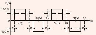
A single-phase inverter is fed from a 100 V dc source and is controlled using a quasi-square wave modulation scheme. The angle \(\sigma\) is adjusted to entirely eliminate the 3rd harmonic component from the output voltage. Under this condition, the magnitude of the 5th harmonic component as a percentage of the magnitude of the fundamental component is \_\_\_\_\_\_\_\_ (rounded off to 2 decimal places).
SSolution
For quasi-square wave modulation:
To eliminate 3rd harmonic: \(V_3 = 0\)
Ratio of 5th to fundamental:
Magnitude: \(\left|\frac{V_5}{V_1}\right| = \frac{1}{5} = 0.2 = \boxed{20.00%}\)$
QQuestion 5 0 Mark
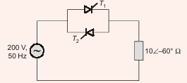
Thyristor \(T_1\) is triggered at angle \(\alpha\) (in degrees), and \(T_2\) at angle \(180° + \alpha\), in each cycle of the sinusoidal input voltage. Assume both thyristors to be ideal. To control the load power over the range 0 to 2 kW, the minimum range of variation in \(\alpha\) is:
AOptions
- \(0°\) to \(60°\) \CorrectChoice \(60°\) to \(180°\)
- \(0°\) to \(120°\)
- \(60°\) to \(120°\)
SSolution
Given: Load impedance \(= 10\angle -60°\) \(\Omega\), Supply \(= 200\) V, 50 Hz
Load: \(Z = 10\angle -60° = 5 + j8.66\) \(\Omega\) (R-L load)
For ac voltage controller with R-L load, maximum power occurs when:
For minimum power (zero): \(\alpha = 180°\)
Therefore, to control power from 0 to maximum (2 kW), the firing angle must vary from:
Correct answer: B
QQuestion 6 0 Mark
A single-phase, full-bridge, fully controlled thyristor rectifier feeds a load comprising a 10 \(\Omega\) resistance in series with a very large inductance. The rectifier is fed from an ideal 230 V, 50 Hz sinusoidal source through cables which have negligible internal resistance and a total inductance of 2.28 mH. If the thyristors are triggered at an angle \(\alpha = 45°\), the commutation overlap angle in degree (rounded off to 2 decimal places) is \_\_\_\_\_\_\_\_.
SSolution
Given: \(V_s = 230\) V, \(f = 50\) Hz, \(\alpha = 45°\), \(R = 10\) \(\Omega\), \(L_s = 2.28\) mH
Average output voltage without overlap:
Load current: \(I_0 = \frac{V_{d0} - \Delta V_d}{R}\)
Voltage drop due to commutation:
Therefore: \(I_0 \times 10 = 146.42 - 4 \times 50 \times 2.28 \times 10^{-3} \times I_0\)
Using overlap equation:
QQuestion 7 0 Mark
A non-ideal Si-based pn junction diode is tested by sweeping the bias applied across its terminals from \(-5\) V to \(+5\) V. The effective thermal voltage, \(V_T\), for the diode is measured to be \((29 \pm 2)\) mV. The resolution of the voltage source in the measurement range is 1 mV. The percentage uncertainty (rounded off to 2 decimal places) in the measured current at a bias voltage of 0.02 V is \_\_\_\_\_\_\_\_.
SSolution
Diode equation: \(I = I_0\left[\exp\left(\frac{V_D}{\eta V_T}\right) - 1\right]\)
Given: \(V_T = (29 \pm 2)\) mV, \(V_D = 20\) mV, \(W_{V_D} = 1\) mV, \(W_{V_T} = 2\) mV
Taking natural log: \(\ln(I) = \ln(I_0) + \frac{V_D}{\eta V_T}\)
For \(\eta = 1\), differentiating:
Uncertainty propagation:
Percentage uncertainty: \(\boxed{5.87%}\)$
QQuestion 8 0 Mark
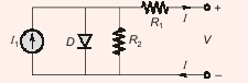
Consider the diode circuit shown. The diode obeys \(I_D = I_S\left[\exp\left(\frac{V_D}{nV_T}\right) - 1\right]\), where \(n > 1\), \(V_T > 0\). The circuit is biased so that \(V > 0\) and \(I < 0\). To transfer maximum power from the current source (\(I_1\)) to a resistive load (not shown) at the output, what values of \(R_1\) and \(R_2\) would you choose?
AOptions
- Small \(R_1\) and small \(R_2\).
- Large \(R_1\) and large \(R_2\). \CorrectChoice Small \(R_1\) and large \(R_2\).
- Large \(R_1\) and small \(R_2\).
SSolution
For maximum power transfer from current source \(I_1\):
Analysis:
- The voltage across the diode: \(V_D = \frac{R_2}{R_1 + R_2} \times V\)
- For maximum power to the load, we need maximum voltage across the diode
- Small \(R_1\) minimizes voltage drop across \(R_1\)
- Large \(R_2\) maximizes the voltage divider ratio
With small \(R_1\) and large \(R_2\): \(V_D \approx V\) (maximum possible)
This ensures maximum voltage and current capability for the load connected across the diode terminals.
Correct answer: C
QQuestion 9 0 Mark
A dc-dc converter circuit with switch \(Q\) switched at a frequency of 10 kHz with a duty ratio of 0.6. All components are ideal, and the initial current in the inductor is zero. Energy stored in the inductor in mJ (rounded off to 2 decimal places) at the end of 10 complete switching cycles is \_\_\_\_\_\_\_\_.
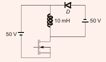
SSolution
Given: Buck-boost converter, \(L = 10\) mH, \(V_{in} = 50\) V, \(V_{out} = 50\) V, \(D = 0.6\), \(f = 10\) kHz
Time period: \(T = \frac{1}{10 \times 10^3} = 100\) \(\mu\)s
During ON time (\(D \cdot T = 60\) \(\mu\)s): Inductor charges
During OFF time (\(D' \cdot T = 40\) \(\mu\)s): Inductor discharges
Current rise per cycle: \(\Delta i_{rise} = 5000 \times 60 \times 10^{-6} = 0.3\) A
Current fall per cycle: \(\Delta i_{fall} = 5000 \times 40 \times 10^{-6} = 0.2\) A
Net rise per cycle: \(0.3 - 0.2 = 0.1\) A
After 10 cycles: \(i_L = 10 \times 0.1 = 1\) A
Energy stored:
QQuestion 10 0 Mark
A non-ideal diode is biased with a voltage of \(-0.03\) V, and a diode current of \(I_1\) is measured. The thermal voltage is 26 mV and the ideality factor for the diode is 15/13. The voltage, in V, at which the measured current increases to \(1.5I_1\) is closest to:
AOptions
- \(-4.50\) \CorrectChoice \(-0.09\)
- \(-0.02\)
- \(-1.50\)
SSolution
Diode equation with ideality factor: \(I = I_0\left[\exp\left(\frac{V_D}{\eta V_T}\right) - 1\right]\)
Given: \(\eta = \frac{15}{13}\), \(V_T = 26\) mV, so \(\eta V_T = \frac{15}{13} \times 26 = 30\) mV
At \(V_{D1} = -0.03\) V \(= -30\) mV:
When current is \(1.5I_1 = 1.5 \times (-0.632 I_0) = -0.948 I_0\):
Correct answer: B