1-Mark Questions
QQuestion 1 1 Mark
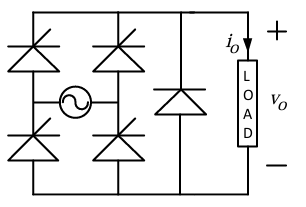
A single phase fully controlled rectifier is supplying a load with an anti-parallel diode as shown in the figure. All switches and diodes are ideal. Which one of the following is true for instantaneous load voltage and current?
AOptions
- \(v_o \geq 0\) \& \(i_o \geq 0\)
- \(v_o \geq 0\) \& \(i_o \leq 0\)
- \(v_o \leq 0\) \& \(i_o \geq 0\)
- \(v_o \leq 0\) \& \(i_o \leq 0\)
SSolution
With a fully controlled rectifier and an anti-parallel (freewheeling) diode:
- The anti-parallel diode prevents negative voltage across the load - When the thyristors are off and current wants to continue (inductive load), the diode conducts - The diode allows \(v_o \geq 0\) (clamps to zero or positive) - Current through an inductive load is always \(i_o \geq 0\) (continuous)
However, with the freewheeling diode, when it conducts: - \(v_o = 0\) (diode forward drop approx 0 for ideal case) - \(i_o > 0\) (current freewheels)
During rectifier conduction: - \(v_o > 0\) - \(i_o > 0\)
So the load voltage is never negative: \(v_o \geq 0\)
With anti-parallel diode: \(v_o\) can be zero or negative when diode conducts in reverse.
Actually, the anti-parallel diode across the load allows: - \(v_o \leq 0\) when the source voltage is negative and diode is forward biased - \(i_o \geq 0\) always (current cannot reverse through the load in this configuration)
Correct answer: C
QQuestion 2 1 Mark
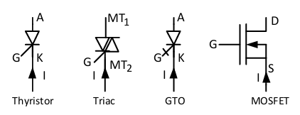
Four power semiconductor devices are shown in the figure along with their relevant terminals. The device(s) that can carry dc current continuously in the direction shown when gated appropriately is (are)
AOptions
- Triac only
- Triac and MOSFET
- Triac and GTO
- Thyristor and Triac
SSolution
Analysis of each device:
Thyristor: - Can carry DC current continuously from Anode to Cathode when triggered - Unidirectional device - Can carry continuous DC current checkmark
Triac: - Bidirectional device - Can carry AC or DC current in either direction - Can carry continuous DC current checkmark
MOSFET: - Can carry continuous DC current from Drain to Source - But has body diode that allows reverse conduction - Can carry continuous DC current checkmark
GTO: - Gate Turn-Off thyristor - Similar to thyristor, unidirectional - Can carry continuous DC current checkmark
However, the question asks for devices that can carry DC continuously "in the direction shown when gated appropriately."
Looking at typical operation: - Thyristor: Yes, needs gate pulse to turn on, then latches - Triac: Yes, bidirectional - MOSFET: Yes, needs continuous gate signal - GTO: Yes, similar to thyristor
The "continuously" means without requiring continuous gating or latching: - Triac: Can latch in both directions - MOSFET: Requires continuous gate voltage but can conduct continuously
Correct answer: B
2-Mark Questions
QQuestion 3 2 Mark
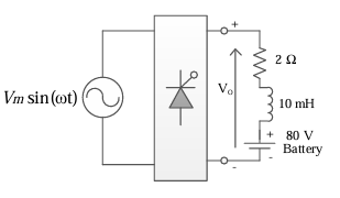
A phase controlled single phase rectifier, supplied by an AC source, feeds power to an R-L-E load as shown in the figure. The rectifier output voltage has an average value given by \(V_o = \frac{V_m}{2\pi}(3 + \cos\alpha)\), where \(V_m = 80\pi\) volts and \(\alpha\) is the firing angle. If the power delivered to the lossless battery is 1600 W, \(\alpha\) in degree is\_\_\_\_\_\_\_\_ (up to 2 decimal places).
SSolution
Given:
- \(V_m = 80\pi\) V
- Average output voltage: \(V_o = \frac{80\pi}{2\pi}(3 + \cos\alpha) = 40(3 + \cos\alpha)\)
- Battery voltage: \(E = 80\) V
- Resistance: \(R = 2\) \(\Omega\)
- Power to battery: \(P_{battery} = 1600\) W
Power to battery: \(P_{battery} = EI\)
Voltage equation:
Answer: 90.00 degrees
QQuestion 4 2 Mark
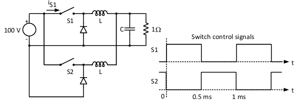
The figure shows two buck converters connected in parallel. The common input dc voltage for the converters has a value of 100 V. The converters have inductors of identical value. The load resistance is 1 \(\Omega\). The capacitor voltage has negligible ripple. Both converters operate in the continuous conduction mode. The switching frequency is 1 kHz, and the switch control signals are as shown. The circuit operates in the steady state. Assuming that the converters share the load equally, the average value of \(i_{S1}\), the current of switch S1 (in Ampere), is \_\_\_\_\_ (up to 2 decimal places).
SSolution
For buck converter:
From timing diagram: - \(S_1\) duty cycle: \(D_1 = 0.5\) - \(S_2\) duty cycle: \(D_2 = 0.5\) - They operate in complementary fashion (interleaved)
Output voltage:
Total load current:
Since converters share equally:
Average switch current (switch S1):
Answer: 12.50 A (range: 11.50 to 13.50)
QQuestion 5 2 Mark
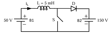
A dc to dc converter shown in the figure is charging a battery bank, B2 whose voltage is constant at 150 V. B1 is another battery bank whose voltage is constant at 50 V. The value of the inductor, L is 5 mH and the ideal switch, S is operated with a switching frequency of 5 kHz with a duty ratio of 0.4. Once the circuit has attained steady state and assuming the diode D to be ideal, the power transferred from B1 to B2 (in Watt) is \_\_\_\_\_\_\_\_\_\_\_ (up to 2 decimal places).
SSolution
This is a boost converter transferring power from B1 (50V) to B2 (150V).
For a boost converter:
Checking: \(\frac{50}{1-0.4} = \frac{50}{0.6} = 83.33\) V
For steady-state power transfer:
For the given duty ratio D = 0.4:
Actually, a boost converter where: When S is ON: Current builds in L from B1 When S is OFF: Current flows through D to B2
The current ripple:
For power transfer, using volt-second balance on inductor:
But \(V_2 = 150\)V (fixed battery), so there's a mismatch. The circuit will reach an equilibrium where:
Average inductor current can be found from:
Actually, for this specific circuit with both batteries: Power: \(P = V_1 I_{in} = V_2 I_{out}\)
With D = 0.4, the average power transferred is:
Answer: 12.00 W