1-Mark Questions
QQuestion 1 1 Mark
A thyristor can be turned ON by:
AOptions
- Forward voltage breakover
- Gate triggering
- Temperature rise
- All of the above
SSolution
A thyristor can be turned ON by: 1. Exceeding forward breakover voltage 2. Applying positive gate current (normal triggering) 3. Excessive temperature (thermal triggering) 4. High dv/dt (not listed but also possible) Correct answer: D.
2-Mark Questions
QQuestion 2 2 Mark
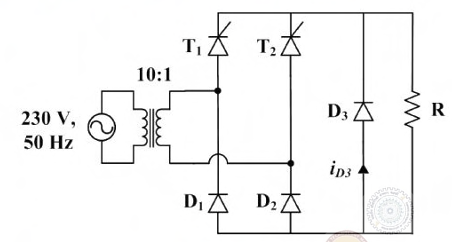
A single-phase full-wave rectifier with center-tapped transformer has an input voltage of 230V RMS. What is the peak inverse voltage (PIV) across each diode?
\begin{figure}[H] \centering
\end{figure}
AOptions
- 230V
- 325V
- 460V
- 650V
SSolution
For a center-tapped transformer, each half has voltage = 230V RMS Peak voltage of each half = \(230 Ã \sqrt{2} = 325V\) PIV across each diode = \(2 Ã 325V = 650V\) Correct answer: D.
QQuestion 3 2 Mark
In a PWM inverter, the total harmonic distortion (THD) can be minimized by:
AOptions
- Increasing switching frequency
- Optimizing switching angles
- Using multiple level inverters
- All of the above
SSolution
THD in PWM inverters can be reduced by: 1. Higher switching frequency (pushes harmonics to higher frequencies) 2. Optimized switching angles (selective harmonic elimination) 3. Multiple level inverters (more levels = lower THD) All methods are effective for THD reduction. Correct answer: D.
QQuestion 4 2 Mark
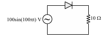
The conduction angle of a thyristor in a single-phase half-wave controlled rectifier with resistive load, when the firing angle is 60°, is: \begin{figure}[H] \centering
\end{figure}
AOptions
- 60°
- 120°
- 180°
- 240°
SSolution
For a resistive load, the thyristor conducts from firing angle (60°) until the current naturally becomes zero at 180°. Conduction angle = 180° - 60° = 120° Correct answer: B.
QQuestion 5 2 Mark
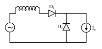
In a DC-DC buck converter operating in continuous conduction mode, the relationship between output voltage and input voltage is: \begin{figure}[H] \centering
\end{figure}
AOptions
- \(V_o = V_{in} Ã D\)
- \(V_o = \frac{V_{in}}{D}\)
- \(V_o = \frac{V_{in}}{1-D}\)
- \(V_o = V_{in} Ã (1-D)\)
SSolution
In a buck converter, the output voltage is: \(V_o = V_{in} Ã D\) where D is the duty cycle (ON time/Total time) This relationship holds for continuous conduction mode. Correct answer: A.