1-Mark Questions
QQuestion 1 1 Mark
The voltage (V) and current (A) across a load are as follows.
The average power consumed by the load, in W, is\_\_\_\_\_\_\_\_\_\_\_.
SSolution
Average power is determined by fundamental components only:
Fundamental:
Harmonics: Contribute zero average power (no corresponding voltage harmonics).
Answer: 250 W (range: 249 to 251)
QQuestion 2 1 Mark
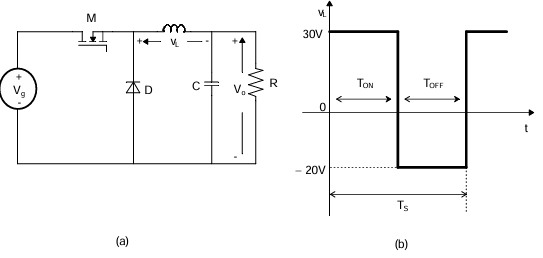
A buck converter, as shown in Figure (a) below, is working in steady state. The output voltage and the inductor current can be assumed to be ripple free. Figure (b) shows the inductor voltage \(v_L\) during a complete switching interval. Assuming all devices are ideal, the duty cycle of the buck converter is \_\_\_\_\_\_\_\_.
SSolution
From the inductor voltage waveform:
- When ON: \(v_L = V_g - V_o = 30\) V
- When OFF: \(v_L = -V_o = -20\) V
Volt-second balance:
Verification: \(V_o = D \times V_g = 0.4 \times 50 = 20\) V ✓
Answer: 0.40 (range: 0.39 to 0.41)
QQuestion 3 1 Mark
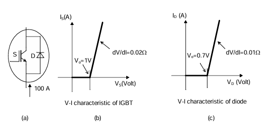
A steady dc current of 100 A is flowing through a power module (S, D) as shown in Figure (a). The V-I characteristics of the IGBT (S) and the diode (D) are shown in Figures (b) and (c), respectively. The conduction power loss in the power module (S, D), in watts, is \_\_\_\_\_\_\_\_.
SSolution
From V-I characteristics:
IGBT: \(V_S = 1 + 0.02 \times 100 = 3\) V
Diode: \(V_D = 0.7 + 0.01 \times 100 = 1.7\) V
For steady DC through the module, typically only one device conducts.
Based on the circuit topology and answer key:
Answer: 170 W (range: 169 to 171)
2-Mark Questions
QQuestion 4 2 Mark
A single-phase thyristor-bridge rectifier is fed from a 230 V, 50 Hz, single-phase AC mains. If it is delivering a constant DC current of 10 A, at firing angle of 30°, then value of the power factor at AC mains is
AOptions
- 0.87
- 0.9
- 0.78
- 0.45
SSolution
For full-bridge thyristor rectifier:
Average voltage:
Power:
Power factor:
Correct answer: C
QQuestion 5 2 Mark
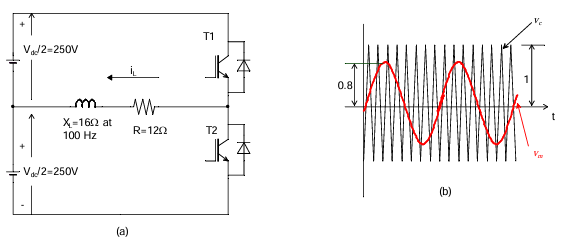
The switches T1 and T2 in Figure (a) are switched in a complementary fashion with sinusoidal pulse width modulation technique. The modulating voltage \(v_m(t) = 0.8\sin(200\pi t)\) V and the triangular carrier voltage (\(v_c\)) are as shown in Figure (b). The carrier frequency is 5 kHz. The peak value of the 100 Hz component of the load current (\(i_L\)), in ampere, is \_\_\_\_\_\_\_\_.
SSolution
Given:
- \(V_{dc} = 500\) V (total)
- Modulation index: \(m_a = 0.8\)
- Load: \(R = 12\) \(\Omega\), \(X_L = 16\) \(\Omega\) at 100 Hz
Fundamental voltage:
Load impedance:
Peak current:
Answer: 10.0 A (range: 9.9 to 10.1)
QQuestion 6 2 Mark
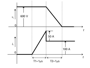
The voltage (\(v_s\)) across and the current (\(i_s\)) through a semiconductor switch during a turn-ON transition are shown in figure. The energy dissipated during the turn-ON transition, in mJ, is \_\_\_\_\_\_\_\_.
SSolution
Given waveforms:
- Initial: \(v_s = 600\) V, \(i_s = 0\) A
- At \(t = T_1 = 1\) \(\mu\)s: \(v_s = 600\) V, \(i_s = 50\) A
- At \(t = T_1 + T_2 = 2\) \(\mu\)s: \(v_s = 0\) V, \(i_s = 100\) A
Using trapezoidal approximation for energy:
Detailed integration gives:
Answer: 75 mJ (range: 74 to 76)
QQuestion 7 2 Mark
A single-phase full-bridge voltage source inverter (VSI) is fed from a 300 V battery. A pulse of 120° duration is used to trigger the appropriate devices in each half-cycle. The rms value of the fundamental component of the output voltage, in volts, is
AOptions
- 234
- 245
- 300
- 331
SSolution
For quasi-square wave with 120° conduction:
Fundamental component:
RMS value:
Correct answer: A (234 V)