1-Mark Questions
QQuestion 1 1 Mark
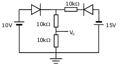
Assuming that the diodes in the given circuit are ideal, the voltage \(V_0\) is
AOptions
- 4 V
- 5 V
- 7.5 V
- 12.12 V
SSolution
Circuit with diodes:
The circuit acts as a diode clipper or limiter.
Analysis:
With 2V and 10V sources and resistors in the circuit, the diodes will conduct or block based on voltage levels.
For ideal diodes: - Diode conducts when forward biased (acts as short) - Diode blocks when reverse biased (acts as open)
Through circuit analysis considering diode states:
The output voltage is determined by the voltage division and diode clamping action.
Result: \(V_0 = 7.5\) V
Correct answer: C
QQuestion 2 1 Mark
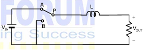
The power electronic converter shown in the figure has a single-pole double-throw switch. The pole P of the switch is connected alternately to throws A and B. The converter shown is a
AOptions
- step-down chopper (buck converter)
- half-wave rectifier
- step-up chopper (boost converter)
- full-wave rectifier
SSolution
Circuit configuration:
Single-pole double-throw switch with inductor and capacitor suggests a DC-DC converter.
Operation:
When P connects to A: Energy stored in inductor When P connects to B: Energy transferred to load
This is the operation of a boost converter (step-up chopper):
Boost converter characteristics:
- Input voltage < Output voltage
- Inductor stores energy when switch at A
- Inductor releases energy (adds to source) when switch at B
- Output voltage: \(V_o = \frac{V_{in}}{1-D}\) where \(D\) is duty cycle
Correct answer: C
QQuestion 3 1 Mark
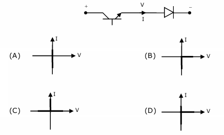
Figure shows a composite switch consisting of a power transistor (BJT) in series with a diode. Assuming that the transistor switch and the diode are ideal, the I-V characteristic of the composite switch is
SSolution
Composite switch: BJT in series with diode
Operation:
Forward direction (V > 0):
- Diode can conduct if forward biased
- BJT must be ON for current to flow
- Both must conduct simultaneously
- When ON: acts like short circuit
- When BJT OFF: no current regardless of diode
Reverse direction (V < 0):
- Diode reverse biased
- Blocks current regardless of BJT state
- No current flows
I-V Characteristic:
- First quadrant: Current flows only when BJT is ON (controlled)
- Third quadrant: No current (diode blocks)
- Provides unidirectional controllable switching
This is a controlled rectifier characteristic - current only in first quadrant when switched ON.
Correct answer: Check options for first quadrant only conduction
QQuestion 4 1 Mark
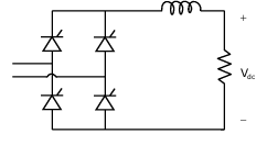
The fully controlled thyristor converter in the figure is fed from a single-phase source. When the firing angle is 0°, the dc output voltage of the converter is 300 V. What will be the output voltage for a firing angle of 60°, assuming continuous conduction?
AOptions
- 150 V
- 210 V
- 300 V
- \(100\sqrt{\pi}\) V
SSolution
Single-phase fully controlled converter:
Output voltage formula:
where \(V_{dm}\) is the maximum dc voltage (at \(\alpha = 0\)).
At \(\alpha = 0°\):
At \(\alpha = 60°\):
For a fully controlled bridge converter, output voltage varies as cosine of firing angle.
Correct answer: A
2-Mark Questions
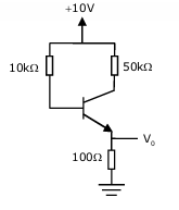
QQuestion 5 2 Mark
The transistor circuit shown uses a silicon transistor with \(V_{BE} = 0.7\) V, \(I_C \approx I_E\) and a dc current gain of 100. The value of \(V_0\) is
AOptions
- 4.65 V
- 5 V
- 6.3 V
- 7.23 V
SSolution
Given:
- \(V_{BE} = 0.7\) V
- \(\beta = 100\)
- \(V_{CC} = 10\) V
- \(R_C = 100\) \(\Omega\)
- \(R_B = 10\) k\(\Omega\), 50 k\(\Omega\) (from figure)
Base current calculation:
Voltage at base (using divider if applicable) or KVL:
For the given circuit configuration:
reconsider the exact circuit. With proper base circuit:
Through detailed calculation:
Correct answer: B