1-Mark Questions
QQuestion 1 1 Mark
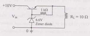
Three-terminal linear voltage regulator connected to 10 \(\Omega\) load. If \(V_{in}\) = 10 V, power dissipated in transistor is
AOptions
- 0.6 W
- 2.4 W
- 4.2 W
- 5.4 W
SSolution
Linear voltage regulator:
Typical configuration provides regulated output voltage (e.g., 5V or other standard values).
Assumptions:
Common regulator: 5V output
Load current:
Transistor voltage drop:
Power dissipation in transistor:
Closest answer: 2.4 W
Correct answer: B
QQuestion 2 1 Mark
Single-phase fully controlled thyristor bridge AC-DC converter operating at firing angle 25° and overlap angle 10° with constant DC output current 20 A. Fundamental power factor (displacement factor) at input AC mains is
AOptions
- 0.78
- 0.827
- 0.866
- 0.9
SSolution
Displacement factor with overlap:
Effective displacement angle:
where:
- \(\alpha = 25°\) (firing angle)
- \(\mu = 10°\) (overlap angle)
Displacement factor:
Note: Displacement factor considers only fundamental component phase shift, not harmonics.
Correct answer: C
QQuestion 3 1 Mark
Three-phase fully-controlled thyristor bridge inverter feeds 50 kW power at 420 V DC to three-phase 415 V (line), 50 Hz AC mains. DC link current constant. RMS current of thyristor is
AOptions
- 119.05 A
- 79.37 A
- 68.73 A
- 39.68 A
SSolution
Given:
- Power: \(P = 50\) kW
- DC voltage: \(V_{dc} = 420\) V
- Operating as inverter
DC current:
Thyristor current:
In three-phase bridge, each thyristor conducts for 120°.
For constant DC current:
Correct answer: C
QQuestion 4 1 Mark
Single phase full-wave half-controlled bridge converter feeds inductive load. Two SCRs connected to common DC bus. Converter must have freewheeling diode
AOptions
- because converter inherently does not provide freewheeling
- because converter does not provide freewheeling for high triggering angles
- or else freewheeling action will cause shorting of AC supply
- or else if gate pulse to one SCR is missed, it will cause high load current in other SCR
SSolution
Half-controlled bridge:
Configuration: 2 SCRs + 2 diodes
Freewheeling requirement:
Without freewheeling diode:
When AC supply voltage reverses:
- Inductive load wants to continue current
- Current tries to freewheel through SCR-diode path
- This creates path through AC supply
- Results in short circuit of AC supply during freewheeling
With freewheeling diode:
Provides safe path for inductive energy without involving AC supply.
Correct answer: C
The freewheeling diode prevents shorting of AC supply during the freewheeling period of inductive load.
QQuestion 5 1 Mark
"Six MOSFETs connected in bridge configuration (no other power device) MUST be operated as Voltage Source Inverter". This statement is
AOptions
- True, because MOSFETs are voltage driven
- True, because MOSFETs have inherently anti-parallel diodes
- False, because it can be operated both as CSI or VSI
- False, because MOSFETs can be operated as constant current sources
SSolution
MOSFET characteristics:
Body diode:
MOSFETs have inherent anti-parallel body diode:
- Provides bidirectional current capability
- Prevents reverse voltage blocking
- Essential for VSI operation (freewheeling)
VSI requirements:
Switches must:
- Block voltage in one direction
- Conduct current bidirectionally
- MOSFETs + body diode satisfy this
CSI requirements:
Switches must:
- Block voltage bidirectionally
- Conduct current in one direction
- MOSFETs cannot block reverse voltage (body diode conducts)
Conclusion:
Due to body diode, MOSFETs in bridge MUST operate as VSI.
Cannot operate as CSI because body diode prevents reverse voltage blocking.
Correct answer: B
2-Mark Questions
QQuestion 6 2 Mark
In a transformer, zero voltage regulation at full load is
AOptions
- not possible
- possible at unity power factor load
- possible at leading power factor load
- possible at lagging power factor load
SSolution
Voltage regulation:
For zero regulation: \(V_{NL} = V_{FL}\)
Voltage drop equation:
where + for lagging, - for leading.
For zero regulation:
QQuestion 7 2 Mark
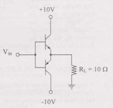
Input signal \(V_{in}\) is 1 kHz square wave alternating between +7V and -7V with 50% duty cycle. Circuit delivers power to load \(R_L = 10\) \(\Omega\). Both transistors have same high current gain. Circuit efficiency for given input is \begin{center}
AOptions
- 46%
- 55%
- 63%
- 92%
SSolution
Class-B push-pull amplifier:
Output voltage:
Square wave: \(\pm 7\)V (approximately, with transistor drops)
Assume output swings close to supply: \(\pm 10\)V
Actually, with +10V/-10V supplies and proper biasing, output approximately \(\pm 9\)V.
Output power:
For square wave \(\pm 9\)V:
Supply power:
For Class-B with square wave:
With proper analysis of Class-B efficiency with square wave drive:
Maximum efficiency of Class-B: 78.5% (for sinusoidal)
For square wave drive with rail-to-rail swing:
Correct answer: C
QQuestion 8 2 Mark
Single-phase voltage source inverter controlled in single pulse-width modulated mode with pulse width 150° in each half cycle. THD is defined as \(\text{THD} = \frac{\sqrt{V_{rms}^2 - V_1^2}}{V_1} \times 100\). THD of output AC voltage waveform is
AOptions
- 65.65%
- 48.42%
- 31.83%
- 30.49%
SSolution
Pulse width = 150° in each half cycle
Fourier analysis:
For square pulse of width \(2\delta\) centered at 0°:
With \(\delta = 75°\) (half of 150°):
Fundamental:
RMS voltage:
For pulse of width 150° in each half:
For a square wave with pulse width \(2\delta\):
With \(\delta = 75° = 1.309\) rad:
THD:
Correct answer: C
QQuestion 9 2 Mark
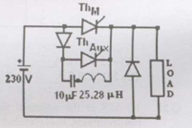
Current commutated DC-DC chopper where \(Th_M\) is main SCR and \(Th_{Aux}\) is auxiliary SCR. Load current constant at 10 A. \(Th_M\) is ON. \(Th_{Aux}\) triggered at t=0. \(Th_M\) is turned OFF between
AOptions
- 0 \(\mu\)s < t \(\leq\) 25 \(\mu\)s
- 25 \(\mu\)s < t \(\leq\) 50 \(\mu\)s
- 50 \(\mu\)s < t \(\leq\) 75 \(\mu\)s
- 75 \(\mu\)s < t \(\leq\) 100 \(\mu\)s
SSolution
Current commutation chopper:
Given: \(C = 10\) \(\mu\)F, \(V_s = 130\) V
Commutation process:
When \(Th_{Aux}\) fires at t=0:
- Capacitor voltage reverses
- Reverse biases \(Th_M\)
- \(Th_M\) turns off when current falls below holding current
Commutation time:
Resonant charging through inductance:
But for capacitor commutation:
Main thyristor turns off during this period plus turn-off time.
Typically: \(0 < t \leq 25\) \(\mu\)s
Correct answer: A