1-Mark Questions
QQuestion 1 1 Mark
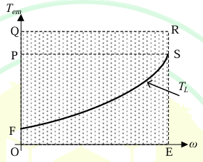
The operating region of the developed torque (\(T_{em}\)) and speed (\(\omega\)) of an induction motor drive is given by the shaded region OQRE in the figure. The load torque (\(T_L\)) characteristic is also shown. The motor drive moves from the initial operating point O to the final operating point S. Which one of the following trajectories will take the shortest time?
AOptions
- \(O - Q - R - S\)
- \(O - P - S\)
- \(O - E - S\)
- \(O - F - S\)
SSolution
To minimize the time taken to move from point O to point S, we need to maximize the accelerating torque throughout the trajectory.
The accelerating torque is given by:
The angular acceleration is:
where \(J\) is the moment of inertia.
For shortest time, we need maximum acceleration, which means we should follow a path where \((T_{em} - T_L)\) is maximum.
Looking at the trajectories:
- Path \(O-Q-R-S\): Follows the upper boundary with maximum torque capability
- Path \(O-P-S\): Intermediate torque path
- Path \(O-E-S\): Lower torque path
- Path \(O-F-S\): Goes below the load characteristic (not possible for motoring)
The path \(O-Q-R-S\) provides the maximum accelerating torque \((T_{em} - T_L)\) throughout the motion, resulting in maximum acceleration and minimum time.
Correct answer: A
QQuestion 2 1 Mark
Instrument(s) required to synchronize an alternator to the grid is/are
AOptions
- Voltmeter
- Wattmeter
- Synchroscope
- Stroboscope
SSolution
For synchronizing an alternator (synchronous generator) to the grid, the following conditions must be satisfied:
- Equal voltage magnitude
- Same frequency
- Same phase sequence
- Correct phase angle (voltages in phase)
Instruments used for synchronization:
- Voltmeter: Checks if the incoming alternator voltage matches the grid voltage
- Synchroscope: Most important instrument - displays the phase angle difference and frequency difference between the alternator and grid. It shows when the voltages are in phase and have the same frequency
- Three lamps method: Alternative method using lamps to check phase relationship
- Frequency meter: Checks frequency matching
A wattmeter is used after synchronization to measure power flow, not for the synchronization process itself.
A stroboscope is used for speed measurement and checking rotating equipment, not for electrical synchronization.
The most appropriate and commonly used instrument for synchronization is the synchroscope, which provides comprehensive information about both frequency and phase angle differences.
Correct answer: C
\textit{Note: In practice, both voltmeter and synchroscope are used together, but the synchroscope is the primary instrument that ensures proper synchronization.}
QQuestion 3 1 Mark
The induced emf in a 3.3 kV, 4 pole, 3-phase star connected synchronous motor is considered to be equal and in phase with the terminal voltage under no load condition. On application of a mechanical load, the induced emf phasor is deflected by an angle of 2° mechanical with respect to the terminal voltage phasor. If the synchronous reactance is 2 \(\Omega\), and stator resistance is negligible, then the motor armature current magnitude, in ampere, during loaded condition is closest to, ____________ (round off to two decimal places).
SSolution
Given:
- Line voltage: \(V_L = 3.3\) kV \(= 3300\) V
- Number of poles: \(P = 4\)
- Star connection
- Load angle (mechanical): \(\delta_m = 2°\)
- Synchronous reactance: \(X_s = 2\) \(\Omega\)
- Stator resistance: \(R_a = 0\) (negligible)
Solution:
Step 1: Convert mechanical angle to electrical angle
Step 2: Calculate phase voltage For star connection:
Step 3: At no load, \(E_f = V_{ph}\) and they are in phase
Under load, the induced EMF \(E_f\) leads the terminal voltage \(V_{ph}\) by load angle \(\delta = 4°\) (for motor operation)
Step 4: Calculate armature current
For a synchronous motor with negligible resistance:
The phasor difference between \(E_f\) and \(V_{ph}\) is:
Taking \(V_{ph}\) as reference:
The voltage difference:
Since \(jI_a X_s = \Delta V\):
Alternatively, using the approximation for small angles:
Answer: 66.52 A
2-Mark Questions
QQuestion 4 2 Mark
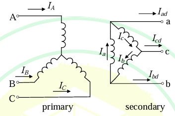
The transformer connection given in the figure is part of a balanced 3-phase circuit where the phase sequence is "\(abc\)". The primary to secondary turns ratio is 2:1. If \((I_a + I_b + I_c = 0)\), then the relationship between \(I_A\) and \(I_{ad}\) will be
AOptions
- \(\displaystyle\frac{|I_A|}{|I_{ad}|} = \frac{1}{2\sqrt{3}}\) and \(I_{ad}\) lags \(I_A\) by 30°.
- \(\displaystyle\frac{|I_A|}{|I_{ad}|} = \frac{1}{2\sqrt{3}}\) and \(I_{ad}\) leads \(I_A\) by 30°.
- \(\displaystyle\frac{|I_A|}{|I_{ad}|} = 2\sqrt{3}\) and \(I_{ad}\) lags \(I_A\) by 30°.
- \(\displaystyle\frac{|I_A|}{|I_{ad}|} = 2\sqrt{3}\) and \(I_{ad}\) leads \(I_A\) by 30°.
SSolution
This is a Delta-Star (ÃŽâ€Â-Y) transformer connection with turns ratio 2:1.
Primary side: Delta connection (ABC)\\ Secondary side: Star connection (abc)\\ Turns ratio: \(N_1:N_2 = 2:1\)
Analysis:
Step 1: Voltage relationship
For Delta-Star connection:
Step 2: Current relationship
For line current \(I_A\) on primary (delta) side and line current \(I_{ad}\) on secondary (star) side:
From ampere-turn balance and connection topology:
Therefore:
Step 3: Phase relationship
For Delta-Star transformer with standard connections:
- Primary line current \(I_A\) is at some reference angle
- Secondary line current \(I_{ad}\) (which is also phase current in star) is related to the primary delta currents
In a ÃŽâ€Â-Y transformer with "abc" sequence:
- If we consider the standard connection where secondary neutral is formed
- The secondary line currents lead the corresponding primary line currents by 30°
However, considering the current transformation from delta to star and the connection shown:
- \(I_A\) flows in the delta winding
- \(I_{ad}\) is reflected from the star side
- Due to the ÃŽâ€Â-Y connection configuration, \(I_{ad}\) leads \(I_A\) by 30°
Correct answer: B
QQuestion 5 2 Mark
A DC series motor with negligible series resistance is running at a certain speed driving a load, where the load torque varies as cube of the speed. The motor is fed from a 400 V DC source and draws 40 A armature current. Assume linear magnetic circuit. The external resistance, in \(\Omega\), that must be connected in series with the armature to reduce the speed of the motor by half, is closest to
\vspace{3cm}
AOptions
- 23.28
- 4.82
- 46.7
- 0
SSolution
Given:
- DC series motor
- Negligible series resistance initially
- Supply voltage: \(V = 400\) V
- Initial armature current: \(I_{a1} = 40\) A
- Load torque: \(T_L \propto N^3\)
- Linear magnetic circuit: \(\phi \propto I_a\)
- Required: Speed to be reduced to \(N_2 = N_1/2\)
Solution:
Step 1: For DC series motor
Initially, with negligible resistance:
Step 2: Back EMF relation
Therefore:
Step 3: Torque relationship
For DC series motor:
Load torque:
At steady state, \(T = T_L\):
Taking ratio:
Step 4: Back EMF at new condition
Step 5: Calculate external resistance
At new condition:
Correct answer: A (23.28 \(\Omega\))
QQuestion 6 2 Mark
A 3-phase, 400 V, 4 pole, 50 Hz star connected induction motor has the following parameters referred to the stator:
\(R_r' = 1\Omega\), \(X_s = X_r' = 2\Omega\)
Stator resistance, magnetizing reactance and core loss of the motor are neglected. The motor is run with constant V/f control from a drive. For maximum starting torque, the voltage and frequency output, respectively, from the drive, is closest to,
AOptions
- 400 V and 50 Hz
- 200 V and 25 Hz
- 100 V and 12.5 Hz
- 300 V and 37.5 Hz
SSolution
Given:
- Rated voltage: \(V = 400\) V (line)
- Rated frequency: \(f = 50\) Hz
- Poles: \(P = 4\)
- Star connection
- \(R_r' = 1\) \(\Omega\), \(X_s = X_r' = 2\) \(\Omega\)
- \(R_s = 0\) (neglected), \(X_m = \infty\) (neglected)
Solution:
Step 1: Torque equation for induction motor
The torque is given by:
where \(X_{eq} = X_s + X_r' = 2 + 2 = 4\) \(\Omega\) (at rated frequency)
At starting, \(s = 1\):
Step 2: Condition for maximum torque
For maximum torque at starting (when \(s = 1\)):
At starting, \(s = 1\):
But reactance \(X \propto f\):
Step 3: Find frequency for maximum starting torque
For maximum starting torque:
Step 4: Find voltage for constant V/f control
With constant V/f control:
At \(f = 12.5\) Hz:
Verification:
At 100 V, 12.5 Hz:
- \(X_{eq} = 4 \times \frac{12.5}{50} = 1\) \(\Omega\)
- \(R_r' = 1\) \(\Omega\)
- Condition \(X_{eq} = R_r'\) is satisfied ✓
This gives maximum starting torque.
Correct answer: C (100 V and 12.5 Hz)
QQuestion 7 2 Mark
Using shunt capacitors, the power factor of a 3-phase, 4 kV induction motor (drawing 390 kVA at 0.77 pf lag) is to be corrected to 0.85 pf lag. The line current of the capacitor bank, in A, is ____________ (round off to one decimal place).
SSolution
Given:
- Line voltage: \(V_L = 4\) kV \(= 4000\) V
- Apparent power: \(S_1 = 390\) kVA
- Initial power factor: \(\cos\phi_1 = 0.77\) (lag)
- Final power factor: \(\cos\phi_2 = 0.85\) (lag)
- 3-phase system
Solution:
Step 1: Calculate real power
Active power (remains constant):
Step 2: Calculate initial reactive power
Or alternatively:
Step 3: Calculate final reactive power
Step 4: Calculate capacitor bank kVAR
Required capacitive reactive power:
Step 5: Calculate line current of capacitor bank
For 3-phase capacitor bank:
Alternative calculation:
Using the formula:
Answer: 9.1 A (rounded to one decimal place)