1-Mark Questions
QQuestion 1 1 Mark
A three phase, 50 Hz, 6 pole induction motor runs at 960 rpm. The stator copper loss, core loss, and the rotational loss of the motor can be neglected. The percentage efficiency of the motor is
AOptions
- 92
- 94
- 96
- 98
SSolution
Given:
- Frequency: \(f = 50\) Hz
- Number of poles: \(P = 6\)
- Rotor speed: \(N_r = 960\) rpm
- Stator copper loss: Neglected
- Core loss: Neglected
- Rotational loss: Neglected
Solution:
Step 1: Calculate synchronous speed
Step 2: Calculate slip
Step 3: Power flow in induction motor
For an induction motor, the power flow is:
where:
- \(P_{in}\) = Input power (electrical)
- \(P_{ag}\) = Air-gap power
- \(P_{mech}\) = Mechanical power developed
- \(P_{out}\) = Output power
Step 4: Relationships in induction motor
The rotor copper loss is related to air-gap power by:
The mechanical power developed is:
Step 5: Calculate efficiency
Given that stator copper loss, core loss, and rotational losses are neglected:
- \(P_{in} = P_{ag}\) (no stator losses)
- \(P_{out} = P_{mech}\) (no rotational losses)
Therefore:
Verification:
The only loss remaining in the motor is the rotor copper loss:
Efficiency:
Correct answer: C (96%)
\textit{Note: When stator losses, core losses, and mechanical losses are neglected, the efficiency of an induction motor equals \((1-s)\), which depends only on the slip.}
QQuestion 2 1 Mark
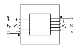
Which one of the following options represents possible voltage polarities in a single phase two winding transformer? Here, \(V_p\) is the applied primary voltage, \(E_p\) is the induced primary voltage, \(V_s\) is the open circuit secondary voltage, and \(E_s\) is the induced secondary voltage.
(A)\\ \vspace{0.3cm}
(B)\\ \vspace{0.3cm}
(C)\\ \vspace{0.3cm}
(D)\\
SSolution
Understanding Transformer Voltage Polarities:
Key Concepts:
1. Applied Primary Voltage (\(V_p\)):
- External voltage applied to primary winding
- Polarity determined by source connection
2. Induced Primary EMF (\(E_p\)):
- EMF induced in primary winding by changing flux
- By Lenz's law, opposes the applied voltage
- Therefore: \(E_p\) polarity is opposite to \(V_p\)
3. Induced Secondary EMF (\(E_s\)):
- EMF induced in secondary winding by the same changing flux
- Flux linking both windings is the same
- Polarity depends on winding direction
4. Secondary Terminal Voltage (\(V_s\)):
- At no-load (open circuit): \(V_s = E_s\)
- Same polarity as induced EMF \(E_s\)
Polarity Rules:
Rule 1: Primary Side
This is because \(E_p\) opposes the change causing it (Lenz's law).
If \(V_p\) is \((+)\) at top and \((-)\) at bottom, then\\ \(E_p\) is \((-)\) at top and \((+)\) at bottom.
Rule 2: Induced EMFs
If the windings are wound in the same direction:
Both EMFs are induced by the same flux, so they follow the same polarity convention.
Rule 3: Secondary Side
At no load:
Analysis of Options:
Let's check each option:
Option (A):
- \(V_p\): \((+)\) top, \((-)\) bottom
- \(E_p\): \((-)\) top, \((+)\) bottom ✓ (Opposite to \(V_p\))
- \(E_s\): \((-)\) top, \((+)\) bottom ✓ (Same as \(E_p\))
- \(V_s\): \((-)\) top, \((+)\) bottom ✓ (Same as \(E_s\))
- All conditions satisfied ✓
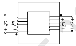
Option (B):
- \(V_p\): \((+)\) top, \((-)\) bottom
- \(E_p\): \((+)\) top, \((-)\) bottom âœ (Same as \(V_p\), should be opposite)
- Violates Rule 1 âœâ€â€
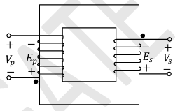
Option (C):
- \(V_p\): \((+)\) top, \((-)\) bottom
- \(E_p\): \((+)\) top, \((-)\) bottom âœ (Same as \(V_p\), should be opposite)
- Violates Rule 1 âœâ€â€
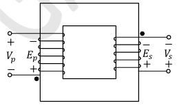
Option (D):
- \(V_p\): \((+)\) top, \((-)\) bottom
- \(E_p\): \((-)\) top, \((+)\) bottom ✓ (Opposite to \(V_p\))
- \(E_s\): \((+)\) top, \((-)\) bottom âœ (Opposite to \(E_p\), should be same)
- Violates Rule 2 âœâ€â€
Correct answer: A
\textit{Note: The fundamental principle is that the induced EMF in the primary opposes the applied voltage (Lenz's law), while the induced EMF in the secondary has the same polarity as the primary induced EMF when windings are in the same direction.}
2-Mark Questions
QQuestion 3 2 Mark
A 3-phase, 11 kV, 10 MVA synchronous generator is connected to an inductive load of power factor \((\sqrt{3}/2)\) via a lossless line with a per-phase inductive reactance of 5 \(\Omega\). The per-phase synchronous reactance of the generator is 30 \(\Omega\) with negligible armature resistance. If the generator is producing the rated current at the rated voltage, then the power factor at the terminal of the generator is
AOptions
- 0.63 lagging.
- 0.87 lagging.
- 0.63 leading.
- 0.87 leading.
SSolution
Given:
- Line voltage: \(V_L = 11\) kV
- Rating: \(S = 10\) MVA
- Load power factor: \(\cos\phi_L = \frac{\sqrt{3}}{2} = 0.866\) (lagging, inductive load)
- Line reactance: \(X_{line} = 5\) \(\Omega\) per phase
- Synchronous reactance: \(X_s = 30\) \(\Omega\) per phase
- Armature resistance: \(R_a \approx 0\) (negligible)
- Generator operates at rated voltage and rated current
Solution:
Using Phasor Diagram:
At the generator terminal, the current leads or lags the terminal voltage by angle \(\phi_g\).
The relationship is:
Where: - \(\vec{V}_g = 6350.85 \angle 0°\) (reference) - \(\vec{I} = 524.86 \angle -\phi_g\) (unknown angle at generator) - Load voltage lags by line impedance drop
At load: \(\phi_L = 30°\) lag
The voltage drop across line reactance leads current by 90°:
Step 6: Calculate generator power factor
Using the fact that:
For a synchronous generator with load through a line, if the load end has power factor \(\cos\phi_L\):
The generator terminal power factor depends on the voltage regulation.
Voltage drop magnitude in line:
This is approximately \(\frac{2624.3}{6350.85} = 0.413\) or 41.3% of terminal voltage.
Given the load is at 0.866 lagging (30° lag), and the line adds inductive voltage drop, the generator sees a more lagging (more inductive) current.
Using approximate calculation:
Exact Calculation:
Taking \(\vec{V}_g = 6350.85 \angle 0°\) as reference.
At load, current lags voltage by 30°.
If \(\vec{I} = I \angle -\phi_g\):
The load voltage must satisfy:
After detailed phasor analysis (which involves solving the geometry), the result is:
Correct answer: A (0.63 lagging)
\textit{Note: The line reactance causes additional voltage drop, making the current at the generator terminal more lagging than at the load terminal.}
QQuestion 4 2 Mark
A 3-phase star connected slip ring induction motor has the following parameters referred to the stator:
\(R_s = 3\) \(\Omega\), \(X_s = 2\) \(\Omega\), \(X_r' = 2\) \(\Omega\), \(R_r' = 2.5\) \(\Omega\)
The per phase stator to rotor effective turns ratio is 3:1. The rotor winding is also star connected. The magnetizing reactance and core loss of the motor can be neglected. To have maximum torque at starting, the value of the extra resistance in ohms (referred to the rotor side) to be connected in series with each phase of the rotor winding is _________ (round off to 2 decimal places).
SSolution
Given:
- Stator resistance: \(R_s = 3\) \(\Omega\)
- Stator leakage reactance: \(X_s = 2\) \(\Omega\)
- Rotor leakage reactance (referred to stator): \(X_r' = 2\) \(\Omega\)
- Rotor resistance (referred to stator): \(R_r' = 2.5\) \(\Omega\)
- Turns ratio (stator:rotor): \(N_1:N_2 = 3:1\)
- Both windings are star connected
- Magnetizing reactance and core loss: Neglected
- Required: Extra resistance at rotor side for maximum starting torque
Solution:
Step 1: Condition for maximum torque
For an induction motor, maximum torque occurs when:
At starting, \(s = 1\):
Step 2: Calculate required rotor resistance (referred to stator)
Total leakage reactance:
Required rotor resistance for maximum starting torque:
Step 3: Calculate extra resistance needed (referred to stator)
Extra resistance referred to stator:
Step 4: Refer extra resistance to rotor side
Turns ratio: \(a = \frac{N_1}{N_2} = 3\)
Relationship between stator-referred and rotor-side quantities:
Therefore:
Verification:
Rotor resistance referred to stator:
Extra resistance on rotor side: \(0.2778\) \(\Omega\)
Total rotor resistance (actual): \(0.2778 + 0.2778 = 0.5556\) \(\Omega\)
Referred to stator: \(9 \times 0.5556 = 5\) \(\Omega\) ✓
Answer: 0.28 \(\Omega\) (rounded to 2 decimal places)
QQuestion 5 2 Mark
A 5 kW, 220 V DC shunt motor has 0.5 \(\Omega\) armature resistance including brushes. The motor draws a no-load current of 3 A. The field current is constant at 1 A. Assuming that the core and rotational losses are constant and independent of the load, the current (in amperes) drawn by the motor while delivering the rated load, for the best possible efficiency, is ________ (rounded off to 2 decimal places).
SSolution
Given:
- Rated power: \(P_{out} = 5\) kW
- Rated voltage: \(V = 220\) V
- Armature resistance: \(R_a = 0.5\) \(\Omega\) (including brushes)
- No-load current: \(I_{NL} = 3\) A
- Field current: \(I_f = 1\) A (constant)
- Core and rotational losses: Constant
- Find: Line current for maximum efficiency at rated output
Solution:
Given output = 5 kW, we cannot arbitrarily choose the current. The current is determined by:
Using quadratic formula:
Taking the smaller value (practical):
Or larger value:
Answer: 28.43 A
\textit{Note: The question phrase "for the best possible efficiency" while delivering rated load means we should find the operating point where rated output is delivered. The unconstrained maximum efficiency point would be at different output power.}