1-Mark Questions
QQuestion 1 1 Mark
The following columns present various modes of induction machine operation and the ranges of slip
\begin{tabular}{|l|l|l|l|} \hline \multicolumn{2}{|c|}{Column A} & \multicolumn{2}{c|}{Column B} \\ \hline & Mode of operation & & Range of Slip \\ \hline a. & Running in generator mode & p) & From 0.0 to 1.0 \\ b. & Running in motor mode & q) & From 1.0 to 2.0 \\ c. & Plugging in motor mode & r) & From -1.0 to 0.0 \\ \hline \end{tabular}
The correct matching between the elements in column A with those of column B is
AOptions
- a-r, b-p, and c-q
- a-r, b-q, and c-p
- a-p, b-r, and c-q
- a-q, b-p, and c-r
SSolution
Understanding Induction Machine Operation Modes:
Key Concept: Slip Definition
For an induction machine:
where:
- \(N_s\) = Synchronous speed
- \(N_r\) = Rotor speed
- \(s\) = Slip
Analysis of Different Operating Modes:
1. Motor Mode (Normal Motoring):
- Rotor speed: \(N_r < N_s\) (rotor runs slower than synchronous speed)
- Slip: \(s = \frac{N_s - N_r}{N_s} > 0\)
- At standstill: \(N_r = 0\), \(s = 1\)
- At synchronous speed: \(N_r = N_s\), \(s = 0\)
- Range: 0 < s < 1 (or 0.0 to 1.0)
- Motor draws power from supply, develops mechanical power
- Torque is positive (in direction of rotation)
Matching: b → p
2. Generator Mode (Generating):
- Rotor speed: \(N_r > N_s\) (rotor runs faster than synchronous speed)
- Slip: \(s = \frac{N_s - N_r}{N_s} < 0\) (negative slip)
- Rotor is driven by prime mover above synchronous speed
- Machine feeds electrical power back to the supply
- Requires external mechanical drive
- Range: -1 < s < 0 (or -1.0 to 0.0)
- Torque is negative (opposes direction of rotation)
Matching: a → r
3. Plugging Mode (Braking):
- Also called "plugged" or "counter-current braking"
- Rotor rotates in opposite direction to rotating magnetic field
- Achieved by reversing phase sequence while motor is running
- Rotor speed: \(N_r < 0\) (negative, opposite to field rotation)
- Slip: \(s = \frac{N_s - N_r}{N_s} = \frac{N_s - (-|N_r|)}{N_s} = \frac{N_s + |N_r|}{N_s} > 1\)
- At maximum negative speed equal to \(-N_s\): \(s = \frac{N_s - (-N_s)}{N_s} = 2\)
- Range: 1 < s < 2 (or 1.0 to 2.0)
- Very high currents, high losses, severe braking torque
- Used for quick stopping or reversing
Matching: c → q
Summary Table:
\begin{tabular}{|l|c|c|c|} \hline Mode & Rotor Speed & Slip Range & Power Flow \\ \hline Generator & \(N_r > N_s\) & \(-1\) to \(0\) & To supply \\ Motor & \(0 < N_r < N_s\) & \(0\) to \(1\) & From supply \\ Plugging & \(N_r < 0\) & \(1\) to \(2\) & From supply (lost as heat) \\ \hline \end{tabular}
Physical Interpretation:
Motor Mode (s = 0 to 1):
- Normal operation
- Slip = 0: No-load, no torque
- Slip = 1: Locked rotor, maximum starting torque
- Typical rated slip: 2-5%
Generator Mode (s = -1 to 0):
- Requires external mechanical power
- Used in regenerative braking
- Wind turbines, overhauling loads
- Slip becomes negative
Plugging Mode (s = 1 to 2):
- Emergency braking
- Very high rotor currents (2-7 times rated)
- High thermal stress on rotor
- Rapid deceleration
- Should be used only briefly
Correct answer: A (a-r, b-p, and c-q)
QQuestion 2 1 Mark
A 10-pole, 50 Hz, 240 V, single phase induction motor runs at 540 RPM while driving rated load. The frequency of induced rotor currents due to backward field is
AOptions
- 100 Hz
- 95 Hz
- 10 Hz
- 5 Hz
SSolution
Given:
- Number of poles: \(P = 10\)
- Supply frequency: \(f = 50\) Hz
- Rated voltage: \(V = 240\) V
- Operating speed: \(N_r = 540\) RPM
- Find: Frequency of rotor currents due to backward field
Solution:
Relative speed between backward field and rotor:
Magnitude: \(1140\) RPM
Slip magnitude:
Step 5: Calculate rotor current frequency due to backward field
Frequency of rotor currents:
For backward field:
Verification:
The rotor current frequency due to forward field would be:
The backward field frequency is much higher because the backward field and rotor move in opposite directions, creating a much larger relative motion.
Physical Explanation:
- Forward field rotates at +600 RPM
- Rotor rotates at +540 RPM
- Relative speed: \(600 - 540 = 60\) RPM
- This produces 5 Hz rotor currents (forward field effect)
- Backward field rotates at -600 RPM
- Rotor rotates at +540 RPM
- Relative speed: \((-600) - (+540) = -1140\) RPM
- Magnitude: 1140 RPM
- This produces 95 Hz rotor currents (backward field effect)
General Formula:
For single-phase induction motor:
where \(s_f\) is the forward slip.
Correct answer: B (95 Hz)
\textit{Note: The backward field in a single-phase induction motor creates a braking torque. The high frequency rotor currents (95 Hz) due to the backward field produce additional losses and reduce motor efficiency.}
QQuestion 3 1 Mark
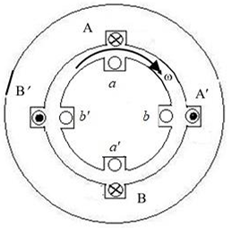
The four stator conductors (A, A', B and B') of a rotating machine are carrying DC currents of the same value, the directions of which are shown in the figure (i). The rotor coils a-a' and b-b' are formed by connecting the back ends of conductors 'a' and 'a" and 'b' and 'b", respectively, as shown in figure (ii). The e.m.f. induced in coil a-a' and coil b-b' are denoted by \(E_{a-a'}\) and \(E_{b-b'}\), respectively. If the rotor is rotated at uniform angular speed \(\omega\) rad/s in the clockwise direction then which of the following correctly describes the \(E_{a-a'}\) and \(E_{b-b'}\)?
\hspace{1cm}
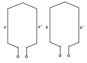
(i): cross-sectional view \hspace{0.1cm} (ii): rotor winding connection diagram\\
AOptions
- \(E_{a-a'}\) and \(E_{b-b'}\) have finite magnitudes and are in the same phase
- \(E_{a-a'}\) and \(E_{b-b'}\) have finite magnitudes with \(E_{b-b'}\) leading \(E_{a-a'}\)
- \(E_{a-a'}\) and \(E_{b-b'}\) have finite magnitudes with \(E_{a-a'}\) leading \(E_{b-b'}\)
- \(E_{a-a'} = E_{b-b'} = 0\)
SSolution
Given:
- Four stator conductors: A, A', B, B' carrying DC currents
- Current directions shown in figure (i)
- Rotor coils: a-a' and b-b'
- Rotor angular speed: \(\omega\) rad/s (clockwise)
- Find: Relationship between induced EMFs
Solution:
Step 1: Analyze magnetic field produced by stator
The stator conductors carry DC currents:
- Conductors A and A' form one pair
- Conductors B and B' form another pair
- DC currents create a stationary magnetic field
From the figure:
- If A has current going into the page (âŠâ€â€) and A' has current coming out (⊙)
- Similarly for B and B'
- This creates a stationary flux pattern
Step 2: Determine nature of the magnetic field
With DC currents in stator conductors:
- The magnetic field is stationary in space
- Field does not rotate
- Field magnitude is constant in time
- Field distribution is fixed in space
Step 3: Analyze EMF induction in rotor coils
For EMF to be induced in rotor coils:
where \(\phi\) is the flux linking the coil.
As the rotor rotates:
- Rotor coil a-a' rotates through the stationary field
- The flux linking coil a-a' changes with position
- Similarly for coil b-b'
Step 4: Calculate flux linkage variation
If the stator creates a sinusoidally distributed stationary field:
For rotor coil at angle \(\theta = \omega t\):
where \(\Phi_m\) is the maximum flux linkage.
Induced EMF:
Step 5: Analyze coil b-b' position
From figure (ii), coil b-b' is positioned at 90° (electrical) from coil a-a':
Induced EMF:
Or:
Step 6: Compare the two EMFs
where \(E_m = \Phi_m \omega\)
This shows:
- Both EMFs have finite magnitudes: \(E_m\)
- \(E_{b-b'}\) leads \(E_{a-a'}\) by 90°
- Same frequency: \(\omega\) rad/s
Physical Interpretation:
- DC stator currents create stationary magnetic field
- Rotating rotor coils cut through this stationary field
- This is the principle of a DC generator or AC generator with DC field
- Coil a-a' experiences maximum flux at one instant
- Coil b-b' (positioned 90° away) experiences maximum flux 90° later in time
- Hence \(E_{b-b'}\) leads \(E_{a-a'}\) by 90° (or \(\frac{\pi}{2}\) radians)
Note on phase relationship:
If the rotor rotates clockwise and coil b-b' is ahead of coil a-a' in the direction of rotation, then b-b' reaches any given flux position before a-a', so \(E_{b-b'}\) leads \(E_{a-a'}\).
\textbf{Correct answer: B (\(E_{a-a'}\) and \(E_{b-b'}\) have finite magnitudes with \(E_{b-b'}\) leading \(E_{a-a'}\))}
\textit{Note: This configuration represents the basic principle of AC generation. The stationary DC field on the stator and rotating rotor coils produce AC voltages. The 90° spatial displacement between rotor coils results in 90° phase difference in induced EMFs.}
QQuestion 4 1 Mark
A separately excited DC motor rated 400 V, 15 A, 1500 RPM drives a constant torque load at rated speed operating from 400 V DC supply drawing rated current. The armature resistance is 1.2 \(\Omega\). If the supply voltage drops by 10% with field current unaltered then the resultant speed of the motor in RPM is ____________ (Round off to the nearest integer).
\vspace{5cm}
SSolution
Given:
- Rated voltage: \(V = 400\) V
- Rated current: \(I_a = 15\) A
- Rated speed: \(N_1 = 1500\) RPM
- Armature resistance: \(R_a = 1.2\) \(\Omega\)
- Supply voltage drops by 10%: \(V_2 = 0.9 \times 400 = 360\) V
- Field current: Constant (unchanged)
- Load: Constant torque
- Find: New speed \(N_2\)
Solution:
Step 1: Calculate initial back EMF
At rated conditions:
Step 2: DC motor speed equation
For a separately excited DC motor:
where:
- \(K\) = machine constant
- \(\phi\) = field flux (constant since field current is unchanged)
- \(N\) = speed in RPM
At rated conditions:
Step 3: Analyze new operating condition
Since load torque is constant and field is constant:
For constant torque and constant flux:
The armature current remains the same because:
- Torque is constant: \(T = K\phi I_a\)
- Field flux is constant: \(\phi =\) constant
- Therefore: \(I_a\) must be constant
Step 4: Calculate new back EMF
With reduced supply voltage:
Step 5: Calculate new speed
From equations (1) and (2):
Verification:
Speed drop:
Percentage drop:
This is reasonable given that voltage dropped by 10%.
Alternative Approach - Using Speed-Voltage Relationship:
For constant torque load with constant field:
Since \(I_a\) is constant:
Physical Explanation:
- When supply voltage drops, back EMF must also drop
- Since \(E = K\phi N\) and flux is constant, speed must drop
- For constant torque, current remains same
- The voltage drop \((I_a R_a = 18\) V) remains constant
- The back EMF (and hence speed) is proportional to \((V - I_a R_a)\)
Answer: 1343 RPM
2-Mark Questions
QQuestion 5 2 Mark
A three-phase synchronous motor with synchronous impedance of 0.1+j0.3 per unit per phase has a static stability limit of 2.5 per unit. The corresponding excitation voltage in per unit is ___________ (Round off to 2 decimal places).
SSolution
Given:
- Synchronous impedance: \(Z_s = 0.1 + j0.3\) pu
- Static stability limit: \(P_{max} = 2.5\) pu
- Find: Excitation voltage \(E_f\) (pu)
Solution:
For synchronous motor with impedance \(Z_s = R_a + jX_s\):
The power transfer is maximum when the load angle satisfies certain conditions. For the maximum power:
\(P_{max} = \frac{VE_f}{|Z_s|} - \frac{V^2 R_a}{|Z_s|^2}\)
With \(V = 1\) pu: \(2.5 = \frac{E_f}{0.3162} - \frac{1 \times 0.1}{0.1}\)
\(2.5 = \frac{E_f}{0.3162} - 1\)
\(\frac{E_f}{0.3162} = 3.5\)
\(E_f = 3.5 \times 0.3162 = 1.11 \text{ pu}\)
Answer: 1.11 pu
\textit{Note: The static stability limit represents the maximum power that can be transferred before the motor loses synchronism. It depends on both the excitation voltage and the synchronous impedance.}
QQuestion 6 2 Mark
A three phase 415 V, 50 Hz, 6-pole, 960 RPM, 4 HP squirrel cage induction motor drives a constant torque load at rated speed operating from rated supply and delivering rated output. If the supply voltage and frequency are reduced by 20%, the resultant speed of the motor in RPM (neglecting the stator leakage impedance and rotational losses) is __________ (Round off to the nearest integer).
\vspace{10cm}
SSolution
Given:
- Rated voltage: \(V_1 = 415\) V (line)
- Rated frequency: \(f_1 = 50\) Hz
- Number of poles: \(P = 6\)
- Rated speed: \(N_1 = 960\) RPM
- Rated power: 4 HP
- Load: Constant torque
- New voltage: \(V_2 = 0.8 \times 415 = 332\) V
- New frequency: \(f_2 = 0.8 \times 50 = 40\) Hz
- Neglect: Stator leakage impedance and rotational losses
- Find: New speed \(N_2\) (RPM)
Solution:
Step 1: Calculate rated synchronous speed and slip
Synchronous speed at rated frequency: \(N_{s1} = \frac{120 f_1}{P} = \frac{120 \times 50}{6} = 1000 \text{ RPM}\)
Rated slip: \(s_1 = \frac{N_{s1} - N_1}{N_{s1}} = \frac{1000 - 960}{1000} = 0.04 = 4%\)
Step 2: Synchronous speed at new frequency
\(N_{s2} = \frac{120 f_2}{P} = \frac{120 \times 40}{6} = 800 \text{ RPM}\)
Step 3: Torque equation for induction motor
For an induction motor, the torque is: \(T = \frac{3V^2 s R_r'}{\omega_s[(R_r')^2 + (sX_r')^2]}\)
where \(\omega_s = \frac{2\pi f}{P/2}\) is the synchronous angular velocity.
Simplifying: \(T \propto \frac{V^2 s}{f}\)
For constant torque and constant \(\frac{V}{f}\) ratio:
Step 4: V/f control analysis
When both voltage and frequency are reduced by the same percentage (20%): \(\frac{V_2}{f_2} = \frac{0.8V_1}{0.8f_1} = \frac{V_1}{f_1}\)
The V/f ratio is maintained constant.
For constant V/f operation with constant torque: - The flux remains approximately constant: \(\phi \propto \frac{V}{f}\) - For constant torque: \(T = K\phi I_r\)
Step 5: Slip relationship
For constant torque operation with constant V/f:
The torque equation simplifies to: \(T \propto \frac{V^2 s}{f \cdot X_r}\)
Since \(X_r \propto f\): \(T \propto \frac{V^2 s}{f \cdot f} = \frac{V^2 s}{f^2}\)
For constant torque: \(\frac{V_1^2 s_1}{f_1^2} = \frac{V_2^2 s_2}{f_2^2}\)
With \(V_2 = 0.8V_1\) and \(f_2 = 0.8f_1\): \(\frac{V_1^2 s_1}{f_1^2} = \frac{(0.8V_1)^2 s_2}{(0.8f_1)^2}\)
\(\frac{V_1^2 s_1}{f_1^2} = \frac{0.64V_1^2 s_2}{0.64f_1^2}\)
\(s_1 = s_2\)
The slip remains the same!
Step 6: Calculate new speed
\(s_2 = s_1 = 0.04\)
\(N_2 = N_{s2}(1 - s_2) = 800(1 - 0.04) = 800 \times 0.96 = 768 \text{ RPM}\)
Verification:
Speed ratio: \(\frac{N_2}{N_1} = \frac{768}{960} = 0.8\)
Frequency ratio: \(\frac{f_2}{f_1} = \frac{40}{50} = 0.8\) ✓
This confirms that under constant V/f control with constant torque: \(N_2 = N_1 \times \frac{f_2}{f_1}\)
Physical Explanation:
When V/f ratio is maintained constant:
- Flux remains constant
- For constant torque, slip remains constant
- Speed is proportional to frequency: \(N = N_s(1-s) \propto f\)
- Reducing frequency by 20% reduces speed by 20%
This is the principle of V/f control (scalar control) used in variable frequency drives.
Answer: 768 RPM
QQuestion 7 2 Mark
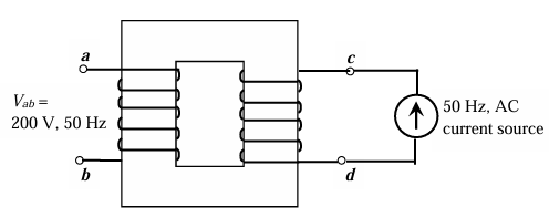
When the winding c-d of the single-phase, 50 Hz, two winding transformer is supplied from an AC current source of frequency 50 Hz, the rated voltage of 200 V (rms), 50 Hz is obtained at the open-circuited terminals a-b. The cross sectional area of the core is 5000 mm\(^2\) and the average core length traversed by the mutual flux is 500 mm. The maximum allowable flux density in the core is \(B_{max} = 1\) Wb/m\(^2\) and the relative permeability of the core material is 5000. The leakage impedance of the winding a-b and winding c-d at 50 Hz are \((5 + j100 \times 0.16)\) \(\Omega\) and \((11.25 + j100 \times 0.36)\) \(\Omega\), respectively. Considering the magnetizing characteristics to be linear and neglecting core loss, the self-inductance of the winding a-b in millihenry is ___________ (Round off to 1 decimal place).
SSolution
Given:
- Frequency: \(f = 50\) Hz
- Winding a-b (primary): Open circuit voltage \(V_{ab} = 200\) V (rms)
- Winding c-d (secondary): Supplied from AC current source
- Core cross-sectional area: \(A = 5000\) mm\(^2 = 5 \times 10^{-3}\) m\(^2\)
- Average core length: \(l = 500\) mm \(= 0.5\) m
- Maximum flux density: \(B_{max} = 1\) Wb/m\(^2\)
- Relative permeability: \(\mu_r = 5000\)
- Leakage impedance of a-b: \(Z_{ab} = 5 + j16\) \(\Omega\)
- Leakage impedance of c-d: \(Z_{cd} = 11.25 + j36\) \(\Omega\)
- Find: Self-inductance of winding a-b (\(L_{ab}\)) in mH
Solution: \(L_m = \frac{N_{ab}^2}{\mathcal{R}} = \frac{32,400}{159.15} = 203.6 \text{ H}\)
\(\mu_0 \mu_r A = 4\pi \times 10^{-7} \times 5000 \times 5 \times 10^{-3}\) \(= 4\pi \times 10^{-7} \times 25 = 31.416 \times 10^{-6} \text{ Hâ‹…m}\)
\(\mathcal{R} = \frac{0.5}{31.416 \times 10^{-6}} = 15,915 \text{ AT/Wb}\)
\(L_m = \frac{32400}{15915} = 2.036 \text{ H} = 2036 \text{ mH}\)
\(L_{ab} = 2036 + 50.9 = 2086.9 \text{ mH}\)
Rounded: \(\mathbf{2086.9 \text{ mH}}\) or approximately \(\mathbf{2087.0 \text{ mH}}\)
Answer: 2087.0 mH
\textit{Note: The high inductance value is due to the high permeability (5000) and relatively large number of turns (180) in the transformer winding.}