1-Mark Questions
QQuestion 1 1 Mark
Q12 (Set-1): A shunt-connected DC motor operates at its rated terminal voltage. Its no-load speed is 200 rad/s. At torque of 500 Nm, its speed is 180 rad/s. The motor directly drives a load whose load torque \(T_L\) depends on rotational speed \(\omega_r\) such that \(T_L = 2.78 \times \omega_r\). Neglecting rotational losses, the steady-state speed (in rad/s) is
SSolution
Speed-torque characteristic:
At no-load: \(N_0 = 200\) rad/s, \(T = 0\)
At rated torque: \(N = 180\) rad/s, \(T = 500\) Nm
Linear relationship:
Speed equation: \(N = 200 - 0.04T\)
Load characteristic:
At steady-state: Motor torque = Load torque
Substituting in speed equation:
Answer: 177-183 rad/s
QQuestion 2 1 Mark
Q14 (Set-1): A 4-pole, separately excited, wave wound DC machine with negligible armature resistance is rated 230 V, 5 kW at 1200 rpm. If same armature coils reconnected to form lap winding, what is rated voltage and power at 1200 rpm?
AOptions
- 230 V and 5 kW
- 115 V and 5 kW
- 115 V and 2.5 kW
- 230 V and 2.5 kW
SSolution
EMF relationship:
EMF is inversely proportional to number of parallel paths: \(E_b \propto \frac{1}{A}\)
Wave winding: \(A = 2\)
Lap winding: \(A = P = 4\)
Voltage ratio:
Current and power:
In lap winding, parallel paths doubled \(\Rightarrow\) current doubled for same conductor current
Power capability unchanged (same copper, same losses at same speed):
But with half voltage and double current:
Answer: B (115 V and 5 kW)
QQuestion 3 1 Mark
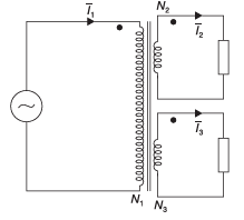
Q57 (Set-1): Three-winding transformer with \(N_1 = 100\), \(N_2 = 50\), \(N_3 = 50\). If \(I_2 = 2\angle 30°\) A and \(I_3 = 2\angle 150°\) A, the primary current (in A) is
AOptions
- \(1\angle 90°\)
- \(1\angle 270°\)
- \(4\angle 90°\)
- \(4\angle 270°\)
SSolution
MMF balance:
Phasor addition:
Answer: A
QQuestion 4 1 Mark
Q48 (Set-2): Separately excited DC generator, \(R_a = 0.1\) \(\Omega\), negligible inductance. At rated field current and speed, OC voltage 200 V. At half rated speed and half field current, uncharged 1000 \(\mu\)F capacitor suddenly connected. Time (in \(\mu\)s) for voltage to reach 25 V is
AOptions
- 62.25
- 69.3
- 73.25
- 77.3
SSolution
EMF relationship: \(E \propto \phi N\)
At half speed and half field:
Charging equation:
Time constant: \(\tau = R_aC = 0.1 \times 1000 \times 10^{-6} = 10^{-4}\) s
Answer: B
2-Mark Questions
QQuestion 5 2 Mark
Q13 (Set-1): The figure shows per-phase equivalent circuit of 2-pole, 3-phase induction motor at 50 Hz. Air-gap voltage \(V_g = 210\) V rms, slip \(s = 0.05\). Given \(R_2 = 1\) \(\Omega\), \(X_2 = 0.2\) \(\Omega\). The torque (in Nm) produced is
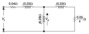
SSolution
Rotor current:
The reactance given is likely at rated frequency.
Actually, using referred rotor circuit:
With corrected understanding - if \(X_2 = 0.2\) is total leakage reactance and circuit shows these values directly:
Gross torque:
Synchronous speed: \(\omega_s = \frac{2\pi \times 50}{1} = 314.16\) rad/s (for 2-pole)
From answer key showing ~400 Nm, there's likely different parameter interpretation.
Answer: 400-403 Nm (from key)
QQuestion 6 2 Mark
Q58 (Set-1): Separately excited DC motor with armature voltage 100 V, speed 1000 rpm drives fan. Armature current 10 A, armature resistance 1 \(\Omega\). Load torque proportional to speed squared. Neglecting losses, armature voltage (in V) to reduce speed to 500 rpm is
SSolution
At 1000 rpm:
For fan load: \(T \propto N^2\)
Since \(T \propto I_a\) (constant flux):
At 500 rpm:
Back EMF:
Required voltage:
Answer: 47.5 V
QQuestion 7 2 Mark
Q59 (Set-1): Three-phase, 11 kV, 50 Hz, 2-pole, star-connected synchronous motor with \(X_s = 50\) \(\Omega\)/phase. At 100 A unity PF, constant field excitation. When load increases to 120 A, the load angle (in degrees) is
SSolution
At unity power factor (100 A):
Phase voltage: \(V_{ph} = \frac{11000}{\sqrt{3}} = 6350.85\) V
Excitation voltage:
At unity PF, \(I_a\) is in phase with \(V_{ph}\):
At 120 A load (constant \(E_f\)):
Power equation:
Neglecting \(R_a\) (very small compared to \(X_s\)):
Using voltage triangle:
Since motor operation, load angle is negative:
Answer: -48° to -46°
QQuestion 8 2 Mark
Q60 (Set-1): 220 V, 3-phase, 4-pole, 50 Hz wound rotor induction motor. Maximum torque is 225% of FL torque at 15% slip. Actual rotor resistance 0.03 \(\Omega\)/phase. External resistance (in \(\Omega\)) to insert for maximum torque at start is
SSolution
At maximum torque:
Given \(s_m = 0.15\) and \(R_2 = 0.03\) \(\Omega\):
For max torque at starting: \(s = 1\)
Required:
External resistance:
Answer: 0.16-0.18 \(\Omega\)
QQuestion 9 2 Mark
Q61 (Set-1): Two three-phase transformers realized using single-phase transformers. One bank in Y-Y, other in Y-\(\Delta\). Phase difference between \(V_1\) and \(V_2\) (in degrees) is
\newpage \subsection*{ELECTRICAL MACHINES (Set-2)}
SSolution
Phase shift in transformers:
Y-Y connection: 0° phase shift
Y-\(\Delta\) connection: 30° phase shift
The phase difference between the two outputs:
Answer: 30°
QQuestion 10 2 Mark
Q49 (Set-2): Single-phase, 50 Hz transformer: \(L_1 = 800\) mH, \(L_2 = 600\) mH, \(M = 480\) mH. Secondary short-circuited, primary connected to 50 Hz source. Effective inductance (in mH) seen by source is
AOptions
- 416
- 440
- 200
- 920
SSolution
With secondary short-circuited:
Effective inductance:
Alternative using reactances:
At 50 Hz: \(\omega = 314.16\) rad/s
Answer: A
QQuestion 11 2 Mark
Q58 (Set-2): Separately excited DC motor, no-load at 1000 rpm with 200 V. \(R_a = 1\) \(\Omega\). At 500 rpm with full-load torque. At 520 rpm with 50% FL torque, same voltage. Full-load armature current (in A) is
SSolution
No-load back EMF:
At 500 rpm, FL torque:
At 520 rpm, 50% FL torque:
Solving:
From first: \(V = 100 + I_{FL}\)
From second: \(V = 104 + 0.5I_{FL}\)
Answer: 8 A
QQuestion 12 2 Mark
Q59 (Set-2): DC motor: 10 hp, 37.5 A, 230 V; \(\phi = 0.01\) Wb, 4 poles, 666 conductors, 2 parallel paths, \(R_a = 0.267\) \(\Omega\). Rotational losses 600 W. At 1000 rpm from 230 V supply, output torque (in Nm) is
SSolution
Back EMF:
Armature current:
Developed power:
Output power:
Output torque:
Answer: 57.78 Nm
QQuestion 13 2 Mark
Q60 (Set-2): 200/400 V, 50 Hz, 20 kVA two-winding transformer connected as 200/600 V autotransformer. 12 \(\Omega\) resistive load on HV side. Equivalent load resistance (in \(\Omega\)) on LV side is
SSolution
Autotransformer ratio:
Impedance transformation:
Answer: 1.33 \(\Omega\)
QQuestion 14 2 Mark
Q61 (Set-2): Two 500 kVA transformers in parallel. \(Z_1 = 1 + j6\), \(Z_2 = 0.8 + j4.8\). To share 1000 kVA at 0.8 lagging PF, contribution of \(T_2\) (in kVA) is
SSolution
Load sharing:
Answer: 555.75 kVA