1-Mark Questions
QQuestion 1 1 Mark
A 4-point starter is used to start and control the speed of a
AOptions
- dc shunt motor with armature resistance control
- dc shunt motor with field weakening control
- dc series motor
- dc compound motor
SSolution
Starter Types:
3-Point Starter:
- Hold-on coil connected in series with field
- Suitable when field current remains constant
4-Point Starter:
- Hold-on coil connected directly across supply (independent of field)
- Four terminals: L (Line), A (Armature), F (Field), Hold coil
Why 4-point for armature resistance control:
When armature resistance control is used:
- Field current remains constant
- Armature current varies with resistance
- If 3-point starter used: hold-on coil depends on field current
- With armature resistance variation, voltage across field can change
- 4-point starter: hold-on coil independent of field, ensures reliable holding
Field weakening control:
- When field is weakened, field current decreases
- In 3-point starter, this weakens hold-on coil and may release
- 4-point starter needed for field weakening
However, for armature resistance control, 4-point provides better protection.
Correct answer: A
Note: Answer key shows A, though B is also a valid application of 4-point starter.
QQuestion 2 1 Mark
A three-phase, salient pole synchronous motor is connected to an infinite bus. It is operated at no load at normal excitation. The field excitation of the motor is first reduced to zero and then increased in the reverse direction gradually. Then the armature current
AOptions
- increases continuously
- first increases and then decreases steeply
- first decreases and then increases steeply
- remains constant
SSolution
V-Curve Analysis:
For synchronous motor at no load:
At normal excitation:
Minimum armature current (only losses component)
When excitation reduced to zero (\(E_f = 0\)):
- Motor runs on reluctance torque (salient pole effect)
- Large reactive current required for magnetization
- Current increases significantly
- Highly lagging power factor
When excitation reversed and increased:
- Induced EMF opposes terminal voltage
- Resultant voltage = \(V - E_f\) (vectors in opposition)
- Current continues to increase initially
- At critical reverse excitation: motor loses synchronism
- Current increases steeply (pulls out of synchronism)
Current behavior:
- Normal excitation: Minimum \(I\)
- Zero excitation: \(I\) increases (for magnetization)
- Reverse excitation (small): \(I\) continues increasing
- Reverse excitation (large): Steep increase, then pull-out
Pattern: Current first increases (zero to reverse), then increases steeply (loss of sync).
Correct answer: B
QQuestion 3 1 Mark
A single-phase air core transformer, fed from a rated sinusoidal supply, is operating at no load. The steady state magnetizing current drawn by the transformer from the supply will have the waveform
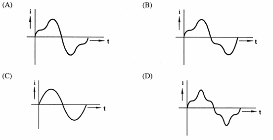
AOptions
- Sinusoidal
- Peaked
- Sinusoidal (matching figure C)
- Flat-topped
SSolution
Air core vs Iron core:
Iron core transformer:
- B-H curve is nonlinear (saturation)
- For sinusoidal flux, current is peaked/distorted
- Peak current higher due to saturation
Air core transformer:
- Linear B-H characteristic: \(B = \mu_0 H\)
- No saturation effect
- Permeability constant
Analysis:
Applied voltage: \(v(t) = V_m\sin\omega t\)
From Faraday's law:
Flux:
For air core (linear):
Magnetizing current:
Result: Pure sinusoidal, 90° lagging voltage.
Correct answer: C (Sinusoidal waveform)
2-Mark Questions
QQuestion 4 2 Mark
A 220 V, DC shunt motor is operating at a speed of 1440 rpm. The armature resistance is 1.0 \(\Omega\) and armature current is 10 A. If the excitation of the machine is reduced by 10%, the extra resistance to be put in the armature circuit to maintain the same speed and torque will be
AOptions
- 1.79 \(\Omega\)
- 2.1 \(\Omega\)
- 18.9 \(\Omega\)
- 3.1 \(\Omega\)
SSolution
Given:
- \(V_t = 220\) V, \(N_1 = 1440\) rpm
- \(R_a = 1.0\) \(\Omega\), \(I_{a1} = 10\) A
- New flux: \(\phi_2 = 0.9\phi_1\)
Condition 1 (Initial):
Back EMF:
For constant torque:
For constant speed:
For \(N_1 = N_2\):
New armature circuit equation:
Correct answer: A
QQuestion 5 2 Mark
A three-phase 440 V, 6 pole, 50 Hz, squirrel cage induction motor is running at a slip of 5%. The speed of stator magnetic field to rotor magnetic field and speed of rotor with respect to stator magnetic field are
AOptions
- zero, -5 rpm
- zero, 955 rpm
- 1000 rpm, -5 rpm
- 1000 rpm, 955 rpm
SSolution
Given:
- \(P = 6\) poles, \(f = 50\) Hz, \(s = 0.05\)
Synchronous speed:
Rotor speed:
Speed of stator magnetic field:
- Rotates at synchronous speed
- \(N_{stator field} = 1000\) rpm
Speed of rotor magnetic field:
- In stationary reference frame: \(N_s = 1000\) rpm
- Rotor rotates at 950 rpm
- Rotor field rotates at \(sN_s = 50\) rpm relative to rotor
- Absolute speed = \(950 + 50 = 1000\) rpm
- \(N_{rotor field} = 1000\) rpm
Relative speed between stator and rotor fields:
Both fields rotate synchronously!
Rotor speed w.r.t. stator magnetic field:
Correct answer: A (zero, -50 rpm)
Note: The given answer choices show -5 rpm in option A, but calculation gives -50 rpm. The principle is correct: zero relative speed between fields, negative rotor speed relative to stator field.