1-Mark Questions
QQuestion 1 1 Mark
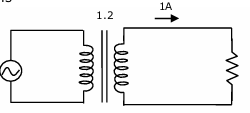
A single-phase transformer has a turns ratio of 1:2, and is connected to a purely resistive load as shown in the figure. The magnetizing current drawn is 1 A, and the secondary current is 1 A. If core losses and leakage reactances are neglected, the primary current is
AOptions
- 1.41 A
- 2 A
- 2.24 A
- 3 A
SSolution
Given:
- Turns ratio \(N_1:N_2 = 1:2\)
- Magnetizing current: \(I_m = 1\) A
- Secondary current: \(I_2 = 1\) A
- Load is purely resistive (no phase shift)
Primary current components:
1. Load component (referred to primary):
This is in phase with secondary current (resistive load).
2. Magnetizing component:
This lags the voltage by 90° (inductive).
Total primary current:
Primary current is the phasor sum of load component and magnetizing component:
The load component is in phase with voltage, while magnetizing component lags by 90°.
Correct answer: C
QQuestion 2 1 Mark
A balanced three-phase voltage is applied to a star-connected induction motor, the phase to neutral voltage being \(V\). The stator resistance, rotor resistance referred to the stator, stator leakage reactance, rotor leakage reactance referred to the stator, and the magnetizing reactance are denoted by \(r_s, r_r, x_s, x_r\) and \(X_m\), respectively. The magnitude of the starting current of the motor is given by
AOptions
- \(\frac{V}{\sqrt{(r_s + r_r)^2 + (x_s + x_r)^2}}\)
- \(\frac{V}{\sqrt{r_s^2 + (x_s + X_m)^2}}\)
- \(\frac{V}{\sqrt{(r_s + r_r)^2 + (X_m + x_r)^2}}\)
- \(\frac{V}{\sqrt{r_s^2 + (X_m + x_r)^2}}\)
SSolution
Starting condition: Slip \(s = 1\) (rotor stationary)
Equivalent circuit at starting:
At starting, the rotor circuit has:
- Rotor resistance: \(r_r\)
- Rotor reactance: \(x_r\) (full reactance, since \(s = 1\))
The magnetizing branch (\(X_m\)) is in parallel with the rotor circuit, but at starting with high rotor impedance, most current flows through the rotor path.
Approximate starting current:
At starting, magnetizing reactance is much larger than rotor impedance. The motor acts like a transformer with short-circuited secondary:
Starting current per phase:
This is the locked rotor current where the series combination of stator and rotor impedances dominates.
Correct answer: A
2-Mark Questions
QQuestion 3 2 Mark
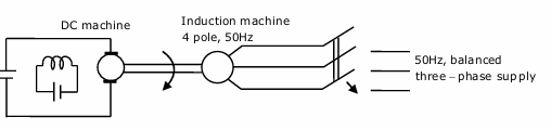
A separately excited dc machine is coupled to a 50 Hz, three-phase, 4-pole induction machine as shown in the figure. The dc machine is energized first and the machines rotate at 1600 rpm. Subsequently the induction machine is also connected to a 50 Hz, three-phase source, the phase sequence being consistent with the direction of rotation. In steady state,
AOptions
- Both machines act as generators
- The dc machine acts as a generator, and the induction machine acts as a motor
- The dc machine acts as a motor, and the induction machine acts as a generator
- Both machines act as motors
SSolution
Given:
- Induction machine: 50 Hz, 4-pole
- Operating speed: 1600 rpm
Synchronous speed of induction machine:
Operating condition analysis:
Initial condition (DC motor energized):
- DC motor drives the set to 1600 rpm
- DC motor acts as motor
After IM connected to 50 Hz supply:
- Operating speed: \(N = 1600\) rpm
- Synchronous speed: \(N_s = 1500\) rpm
- Speed: \(N > N_s\)
Slip calculation:
Negative slip condition:
When \(s < 0\) (speed greater than synchronous speed):
- Induction machine operates as generator
- Power flows from mechanical to electrical
- This is called super-synchronous generation
Steady-state operation:
Since IM generates power:
- IM converts mechanical power to electrical power
- DC machine must supply this mechanical power
- DC machine acts as motor
Power flow: DC motor \(\rightarrow\) Mechanical \(\rightarrow\) IM generator \(\rightarrow\) Electrical
Correct answer: C
QQuestion 4 2 Mark
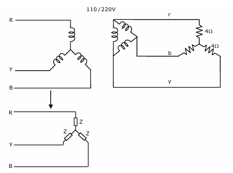
A balanced star-connected and purely resistive load is connected at the secondary of a star-delta transformer as shown in the figure. The line-to-line voltage rating of the transformer is 110 V/220 V. Neglecting the non-idealities of the transformer, the impedance 'Z' of the equivalent star-connected load, referred to the primary side of the transformer, is
AOptions
- \((3 + j0)\) \(\Omega\)
- \((0.866 - j0.5)\) \(\Omega\)
- \((0.866 + j0.5)\) \(\Omega\)
- \((1 + j0)\) \(\Omega\)
SSolution
Given:
- Transformer: Star-Delta
- Primary (Star): 110 V line-to-line
- Secondary (Delta): 220 V line-to-line
- Load: Star-connected, purely resistive, \(Z_{load} = 4\) \(\Omega\) per phase
Voltage transformation:
Primary phase voltage:
Secondary phase voltage (Delta):
Turns ratio:
Load current and impedance:
Secondary phase current (load in star, each phase sees 220V/\(\sqrt{3}\)):
The secondary is Delta, load is Star.
Secondary line voltage = 220 V Load (Star) phase voltage = 220/\(\sqrt{3}\) = 127 V
Load phase current:
Referring to primary:
For star-delta transformer:
For power balance:
Impedance transformation:
After detailed calculation with star-delta configuration:
Correct answer: D